
Advanced Field Test Methods Identifies Problem Root Cause
Summary
Following an overspeed event in 2022, the unit experienced progressively worsening sub-synchronous vibration (SSV), elevated T2 bearing vibration, and repeated high-vibration trips. Previous corrective actions by others, including bearing replacement, shimming, rotor and coupling balance checks, alignment adjustments, and turbine seal modifications, provided only temporary improvement.
In 2026, Mechanical Solutions (MSI) was contracted to determine the problem root cause and to provide specific recommendations to solve the steam turbine-gearbox-generator train problem.
MSI conducted a comprehensive field investigation a combination of test methods including Continuous Monitoring (Figures 1, 5, and 6), TrakVue® video (Figures 2 to 4), Experimental Modal Analysis (EMA, impact), and Operating Deflection Shape (ODS, Figures 7 to 9).
The combined results indicated that excessive lateral flexibility of the T2 bearing pedestal/support system was the primary contributor to the recurring vibration. MSI recommended inspecting and reinforcing the T2 support system, evaluating residual rotor imbalance, and repeating vibration testing after corrective action.
Why was the steam turbine experiencing repeated high-vibration trips?
Unit 10 was originally installed in the early 2000s and had operated for many years without significant recurring vibration problems. However, after the 2022 overspeed event, the turbine began experiencing repeated high-vibration trips, primarily associated with the T2 bearing.
A persistent sub-synchronous vibration component near approximately 32 Hz was also observed. Investigations performed between 2022 and 2025 consistently identified elevated T2 vibration and recurring SSV, particularly as the turbine accelerated through its first critical speed.
From 2022 through 2025 (before MSI involvement), several corrective actions were attempted, including on a trial and error basis:
- Turbine-to-gearbox and generator alignment adjustments
- Steam inlet alignment corrections T2 bearing inspection and replacement
- Changing the bearing from a tilt-pad to pressure-sleeve type
- T2 shimming
- Rotor and coupling balance checks
- Turbine seal modifications
While some of the above measures temporarily improved operation, the elevated T2 vibration and SSV eventually returned. Usually, this type of misalignment and/or balance “sensitivity” may indicate a resonance related issue.
What did MSI’s steam turbine vibration testing reveal?
A timeline of the trip issue is shown in Figure 1. MSI’s TrakVue® Video Position-Change Testing kit was used to eliminate drivetrain misalignment as the problem root cause (Figures 2 to 4).
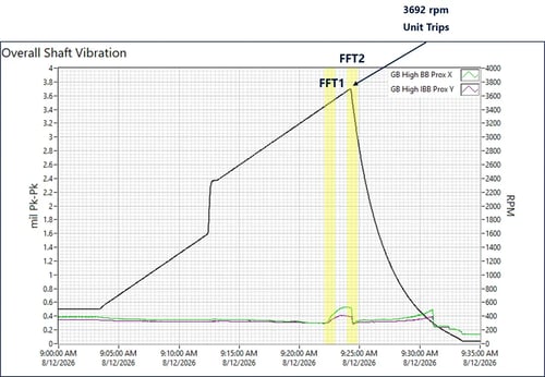
Figure 1: Continuous monitoring test over a 35 minute period during turbine startup. The above plot shows the proximity probe shaft vibration displacement at the gear box high speed pinion (steam turbine side) as the unit trips at 3592 rpm on its way to full speed.
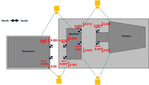
Figure 2: MSI’s TrakVue® Video Position-Change Testing kit was used to dismiss drivetrain misalignment as the problem root cause. The above is a top view of the train component final lateral and axial locations during operation. A similar plot was produced showing the vertical movement.
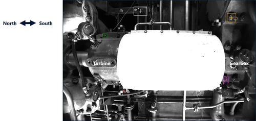
Figure 3: Top view of the turbine-generator coupling area from a TrakVue® optical sensor (camera). indicated relatively small positional changes of the turbine and gearbox over a 20 plus hour operating period. Vertical movement was minimal, approximately 4 mils or less, while localized horizontal and axial movement reached approximately 20 mils
Figure 4: TrakVue® video from a past project showing relative machinery growth over a 12-hour period during a steam turbine-generator startup.
MSI determined that the primary contributors to the vibration problem were:
- a sub synchronous rotor critical speed near one-half of rpm (Figure 5) inducing
- light or intermittent (non-linear) internal rubbing (Figure 6) exasperating
- the excessive lateral flexibility of the T2 pedestal/support system (Figures 7 to 9)
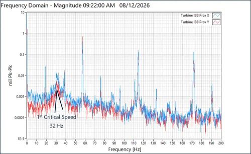
Figure 5: Continuous Monitoring FFT spectra of the T2 shaft before a trip. These results show a sub-synchronous vibration (SSV) component coincident with approximately 1/3x rpm and 1/2x rpm. The presence of these discrete sub-synchronous components is consistent with a problem contributor - light internal rubbing condition within the rotating assembly. This blog provides a more background info about the plot shown above.
Figure 6: Shaft orbit plots viewed from the drive end towards the generator. The plots exhibited multiple-loop and unstable orbital motion, along with multiple keyphasor reference points distributed around the orbit near trip rpm. This behavior indicates nonlinear, non-synchronous shaft motion accompanied by phase instability. In MSI’s opinion, when considered together with the observed sub-synchronous vibration components, this orbital behavior is consistent with a light or intermittent internal rubbing condition within the rotating assembly.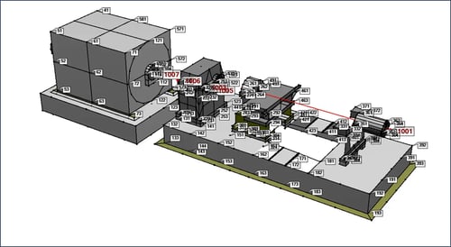
Figure 7: The ODS test involved carefully recording vibration with triaxial accelerometers at over several hundred different locations on the drive-train system including the nearby floor and piping. Shaft proximity probe data was also included in the ODS animation. The CAD model shown above is quickly prepared by MSI based on field measurements and available drawings.
Figure 8: The vibration data is overlaid on the CAD model and animated showing the vibration and motion at each measurement point. Problem primary root cause is horizontal rocking of the turbine T2 bearing and support structure. ODS animation at 1xrpm (3896 rpm or 56.6Hz) shows the upper flexible portion of the support structure’s dynamic motion that is consistent with all of the test results.
Figure 9: ODS animation based on measured test data (not an FEA simulation) showing relative and exaggerated motion of the drive-train system. While the primary issue the rocking motion at the T2 bearing support, noticeable separation between the foundation and floor was also observed (a typical “aging plant” issue).
The reduced T2 pedestal stiffness allowed the turbine rotor excitation (residual imbalance) to produce significant side-to-side motion of the T2 bearing housing during startup causing the turbine to trip. As turbine speed increased toward its normal 3,592 RPM, a discrete SSV component near 30.8 Hz increased substantially and approached the first lateral critical speed of the turbine rotor near 32 Hz, contributing to the elevated vibration and subsequent unit trip shown in Figure 1.
How did MSI diagnose the turbine vibration problem?
MSI performed a comprehensive field investigation to evaluate the rotor-bearing system, support structure, and drivetrain dynamics.
Test methods included:
- TrakVue® was conducted to evaluate thermal growth and alignment changes during startup.
- Experimental Modal Analysis (EMA) or impact testing was used to identify the locations of the T1 and T2 support system natural frequencies.
- Continuous Monitoring (CM) helped MSI evaluate the vibration behavior of the system during operation, identify dominant excitation frequencies, approximately locate the turbine rotor first natural frequency, and determine the locations exhibiting the highest vibration response.
- Operating Deflection Shape (ODS) was performed while the turbine-generator system was operating to visualize the absolute motion of the system at selected frequencies, to identify potential structural or operational issues, and to confirm the turbine rotor first natural frequency.
The analysis of a combination of advanced vibration test results allowed MSI to determine the problem root cause.
Did structural testing identify excessive T2 support flexibility?
TrakVue® testing also did not indicate significant turbine-to-gearbox displacement consistent with misalignment being the primary source of the vibration.
Yes. ODS and impact testing supported the conclusion that the T2 support system had excessive lateral flexibility rather than a significant horizontal structural resonance being the primary cause.
The testing showed that the support structure could permit substantial lateral T2 bearing-housing movement in response to rotor excitation.
These findings helped narrow the troubleshooting focus from potential bearing, alignment, and drivetrain issues toward the T2 bearing support and rotor-support interaction.
What corrective action did MSI recommend?
MSI recommended increasing the lateral stiffness of the T2 bearing support system.
Before implementing structural modifications, the T2 pedestal and associated components should be thoroughly inspected for cracking, looseness, deterioration, or other deficiencies that may have resulted from the 2022 overspeed event.
The inspection should include:
- T2 pedestal
- Flex plates
- Welded connections
- I-beam support
- Fasteners
- Structural interfaces
Any identified deficiencies should be corrected before additional stiffening is implemented.
If no significant structural defects are identified, potential reinforcement measures include diagonal bracing, turnbuckles, and additional gusseting to increase lateral stiffness. Finite Element Analysis (FEA) by MSI should be utilized the design the solution after calibrating the “as built” FEA model with the test results.
How can the source of the turbine vibration be further isolated?
If operationally feasible and approved by the equipment manufacturer and site, MSI recommends operating the turbine uncoupled from the gearbox to determine whether the elevated vibration and SSV remain present under no-load conditions.
This testing could help distinguish vibration originating within the turbine rotor-bearing/support system from excitation transmitted through the gearbox, generator, or coupled drivetrain.
The site should also evaluate and, if necessary, reduce the turbine rotor's residual imbalance to minimize 1x rotational excitation acting on the flexible T2 support.
How should the turbine be verified after corrective action?
Following completion of the recommended corrective actions, MSI recommends repeating vibration testing throughout the operating speed range.
The follow-up testing should verify that:
- T2 lateral motion has been reduced
- 1x rotational vibration has been reduced
- Sub-synchronous vibration has been reduced
- Overall vibration levels have improved
- The turbine can reliably operate through its required speed range
This testing will help confirm whether the increased T2 support stiffness successfully addresses the underlying vibration mechanism.
Frequently Asked Questions
What causes sub-synchronous vibration in a steam turbine?
Sub-synchronous vibration can be associated with rotor instability, internal rubbing, bearing effects, fluid-induced forces, structural flexibility, and interactions within the rotor-bearing-support system. Identifying the specific cause requires detailed vibration testing often times supported by rotordynamics analysis.
How is steam turbine vibration diagnosed?
Steam turbine vibration can be diagnosed using shaft vibration analysis, continuous monitoring, orbit and phase analysis, impact and ODS testing, balance checks, alignment verification, and motion visualization.
Can a flexible bearing support increase turbine vibration?
Yes. A flexible bearing support can allow increased bearing-housing movement in response to rotor excitation. The effect can become more significant when the machine approaches a critical speed.
What is Operating Deflection Shape testing?
ODS testing measures and visualizes how a machine or structure moves during operation. It can help identify excessive structural flexibility and dynamic motion contributing to rotating equipment vibration.
What is Experimental Modal Analysis (Impact) testing?
EMA evaluates a structure's natural frequencies, damping, and mode shapes. It can help determine whether structural characteristics are contributing to vibration problems.
How can recurring steam turbine vibration be reduced?
Corrective action depends on the source of the vibration. Potential solutions include increasing support stiffness, correcting structural deficiencies, balancing the rotor, addressing rubbing or seal issues, and correcting alignment or operating conditions.
Do you need help troubleshooting recurring turbomachinery vibration? MSI combines vibration analysis, rotordynamics, structural testing, and advanced motion visualization to identify and resolve complex rotating equipment problems.