Improving Cost of Ownership With Vibration Risk Reduction: Part 1 of 2
Summary
Vibration risk reduction helps plant owners, engineering firms, and contractors identify machinery dynamics problems before machinery installation, startup, commissioning, and long-term operation. For new or modified pump stations, excessive vibration can lead to premature seal and bearing failure, piping fatigue, structural resonance, schedule delays, and costly corrective work.
This case history emphasizes that addressing vibration and dynamics issues during plant design can lead to smoother commissioning and lower lifecycle cost of ownership.
What are the three steps for reducing vibration risk in a pump station?
With reference to Figure 1:
1) Plant design assessment during the 30%–90% design phase: This may include pre-modification testing when an existing plant or machinery system is being modified including machinery replacement.
2) Pre-installation rotating machinery dynamics analysis: This should be performed shortly after pumps or other rotating machinery are purchased.
3) Post-installation Vibration Acceptance Testing (VAT) or vibration verification testing: This should be completed before the plant is turned over to the owner (VAT is discussed in the Part 2 case history).
This process helps identify structural and acoustic natural frequencies and potential resonance, piping vibration, and foundation-related risks before they cause commissioning delays or long-term reliability problems.
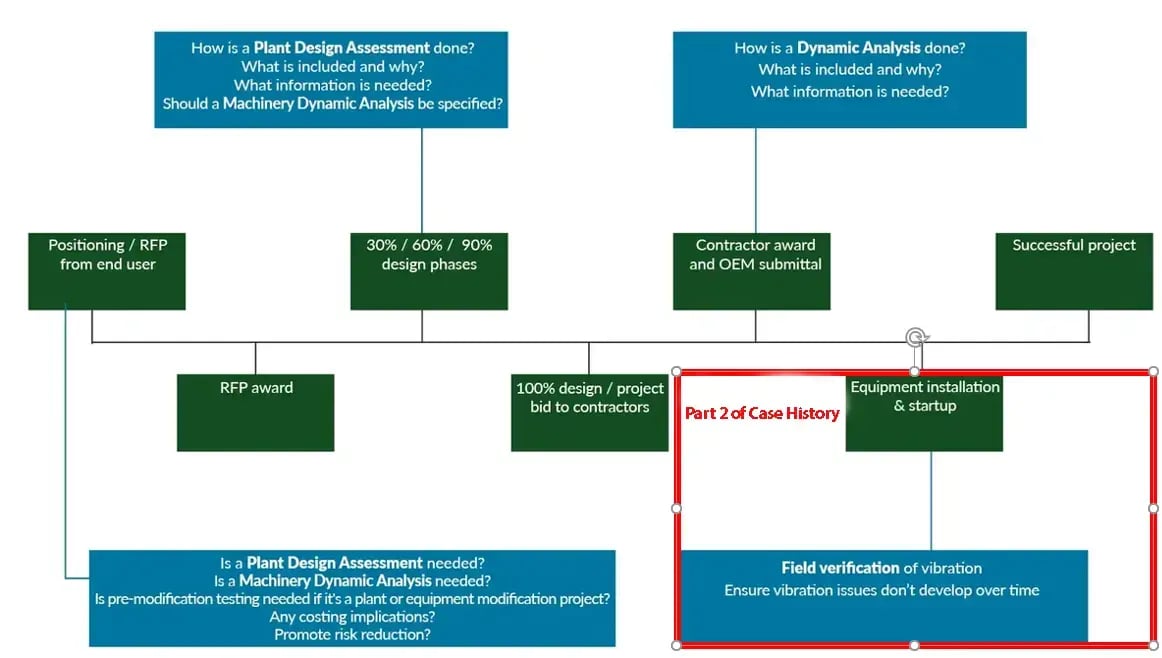
Figure 1. When should vibration expertise be used in a plant design project? Vibration risk reduction should begin during the RFP and design phases, continue through machinery dynamics analysis, and conclude with post-installation vibration verification testing before plant turnover.
Vibration risk reduction lowers plant cost of ownership by identifying potential pump, piping, foundation, and structural resonance issues before equipment startup. The most effective approach includes plant design assessment, rotating machinery dynamics analysis, and post-installation vibration verification testing.
Why Should Vibration Risk Be Addressed Before Pump Station Startup?
New or modified pump, and other rotating machinery systems (Figure 2), often experience reliability problems during startup when vibration risks are not addressed early. Excessive vibration can cause premature seal failure, bearing failure, piping fatigue, catastrophic damage, and plant inoperability. Correcting these problems during commissioning can increase project costs and create schedule delays.
When Should Vibration Expertise Be Used in a Plant Design Project?
Vibration expertise should be applied before construction, not after vibration problems appear in the field. The most valuable time to begin vibration risk reduction is during the proposal and design process, when engineering firms and contractors are preparing their response to a Request for Proposal.
 Figure 2. What machinery systems benefit from vibration risk reduction? Pumps, centrifuges, blowers, mixers, and other rotating machinery systems can benefit from early vibration risk assessment, especially when installed on elevated structures, tall supports, or with complex piping systems.
What Plant Conditions Increase the Risk of Pump Vibration Problems?
Some plant designs are more vulnerable to vibration and machinery dynamics problems than others. A vibration risk reduction plan is especially valuable when a project includes:
-
- Equipment mounted on elevated structures or upper floors
- Long vertical or horizontal pipe runs
- Tall mounting piers for rotating machinery, such as pumps, centrifuges, mixers, and blowers.
- Larger machinery, new machinery, or new machinery layouts
- Designs that must accommodate future flow requirements or staged installations (Figure 3).
How Does Plan Design Assessment Reduce Vibration Risk?
A plant design assessment uses machinery dynamics expertise to evaluate the interaction between rotating equipment, foundations, floors, building structures, and piping. During the 30%–90% design phase, dynamics experience and finite element analysis can be used to evaluate notional equipment system designs before construction is finalized. This helps identify structural natural frequency issues before concrete is poured.
Why Is the 60% Design Phase Important?
The 60% design phase is often an ideal point to evaluate structural natural frequency, acoustic resonance, foundation stiffness, and piping layout risks. At this stage, the design is mature enough for meaningful analysis, but still flexible enough for engineering changes before construction costs escalate.
 Figure 3. How can FEA identify structural natural frequency risks before construction? Finite element analysis during the 60% design phase can identify structural and acoustic resonance risks before plant design is finalized.
What Is Rotating Machinery Dynamics Analysis?
Rotating machinery dynamics analysis evaluates whether the final equipment, structure, and piping as it will be installed contain problematic lateral or train torsional rotordynamic natural frequencies or system natural frequencies. Mechanical Solutions recommends performing this analysis before equipment manufacturing, when changes are still easier and less expensive to make.
Why Must the Whole Machinery System Be Included?
Physics. A rotating machinery train does not operate in isolation. The full machinery system (Figures 4 and 5) includes the rotating equipment, support structure, floor, portions of the building, nearby piping, acoustics, water level, and multi-machine operating conditions with or without variable rotating speed. The interaction between these system elements establishes the “as installed” natural frequencies and the potential for high vibration due to acoustic or structural resonance. This case history warns that incomplete system assumptions can lead to inaccurate structural dynamics predictions; in one example, Mechanical Solutions identified a 32% difference in structural natural frequency caused by poor assumptions.
Rotating machinery dynamics analysis should include the equipment, foundation, support structure, floor, nearby piping, acoustic effects, water level, and operating conditions. Excluding these factors can produce inaccurate vibration predictions and increase the risk of resonance.
Which Standards Help Specify Pump System Dynamics Analysis?
Specification writers can use recognized standards and guidelines to reduce the risk of damaging vibration. The case history references ISO vibration guidance, ANSI/Hydraulic Institute guidance, and American Petroleum Institute standards.
For external-link support, ANSI/HI 9.6.8 describes how to evaluate pumping machinery construction attributes and site characteristics to determine dynamic performance effects on equipment life and reliability. ISO guidance establishes general guidelines for measuring and evaluating machinery vibration on rotating and non-rotating parts of complete machines. API 610 specifies requirements for centrifugal pumps used in petroleum, petrochemical, and natural gas industry process services.
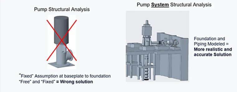
Figure 4. Why should vibration analysis include the full machinery system? Accurate pump system dynamics analysis should include the foundation, building structure, support floor, nearby piping, and other connected components.
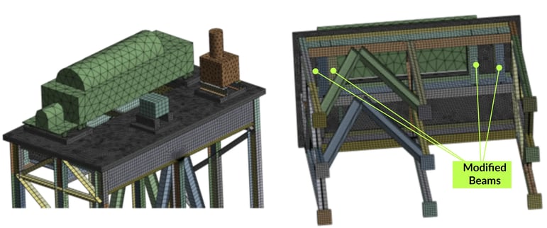
Figure 5. How can pre-modification testing prevent resonance problems? For an existing building modification, pre-modification testing and structural analysis helped identify support-structure changes that reduced the risk of missed resonance issues.
Frequently Asked Questions
What is vibration risk reduction?
Vibration risk reduction is the process of identifying and correcting potential machinery dynamics, structural resonance, piping vibration, and foundation issues before startup or commissioning. It helps reduce the likelihood of premature equipment failure, plant downtime, and costly field modifications.
When should vibration risk reduction begin?
Vibration risk reduction planning should begin during the RFP and early design phases. This case history recommends applying vibration expertise during plant design assessment, pre-installation rotating machinery dynamics analysis, and post-installation vibration verification testing.
Why is pump vibration a cost-of-ownership issue?
Pump vibration can increase cost of ownership by causing seal failure, bearing failure, piping fatigue, unplanned downtime, commissioning delays, and corrective construction work. Addressing vibration risk during design is less disruptive than correcting problems after installation.
What is a plant design assessment?
A plant design assessment evaluates whether the equipment, foundation, floor, piping, and surrounding structure are likely to create vibration or resonance problems. It is commonly performed during the 30%–90% design phase.
What is rotating machinery dynamics analysis?
Rotating machinery dynamics analysis evaluates the dynamic behavior of pumps, centrifuges, and other rotating equipment, including lateral natural frequencies, torsional natural frequencies, structural natural frequencies, and system-level interactions.
Why is Finite Element Analysis useful for vibration risk reduction?
Finite Element Analysis helps engineers evaluate structural natural frequency, mode shapes, foundation stiffness, and support-structure behavior before construction or equipment manufacturing. This allows design changes to be made earlier in the project.
What is post-installation vibration verification or Vibration Acceptance Testing (VAT)?
Post-installation vibration verification testing confirms that installed machinery operates within acceptable vibration levels before the plant is turned over to the owner. It is the final check that the installed system performs as intended.

