A manufacturer of an innovative spinal implant approached MSI for help in assessing the implant’s structural integrity. Of concern was not only the ability of the implant to withstand the forces during deployment, but also to withstand the in vivo physiologic loading. The stent-like implant is to function as a mechanical barrier to the escape of nuclear material as would occur during disc herniation.
The spinal disc presents a challenging mechanical environment due to its compliant nature and large deformations. This intradiscal implant must deform along with the disc as it augments the strength of the annulus. Another challenge to the strength of the implant is the curved trajectory that the implant must take during insertion to the proper location in the disc. In order to evaluate the deployment and in vivo stress levels a three-dimensional finite element analysis was performed. The sliding frictional contact capabilities and the nonlinear material property features of the ANSYS program were employed.
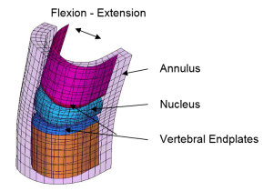 FEA model of spinal segment test fixture
The analysis was performed in several steps. The disc deformations were first established using an idealized model of the nucleus, annulus and vertebral endplates. The model shown above in simulates the fatigue test fixture comprised of polyurethane components. Although it differs somewhat from actual spinal anatomy, it does capture the important load conditions for a fatigue assessment. Sliding contact was modeled between the annulus, nucleus, and endplates. The nucleus was modeled as nearly incompressible. The spinal segment was then put through a variety of movements including combinations of compression, flexion-extension and lateral bending. Realistic bulging deformations of the nucleus were ultimately predicted by the model.
]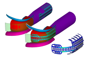 FEA model and strain results for deployment
The FEA model of the implant was inserted and then forced to move within the space between the nucleus and annulus as the spinal segment flexed and extended. Initial models exhibited very high strains primarily due to the insertion. Subsequent redesigns resulted in acceptable strain levels for both deployment and cyclic in vivo behavior. Additional analyses were performed with a simulated defect in the annulus, an expected scenario. Applied pressure would tend to bulge the nucleus out through the annular defect. The barrier was found to inhibit this bulging.
