Field Testing and Troubleshooting
Use Advanced Test Methodology Coupled with Analysis to Solve High-Value Problems While Avoiding Costly Trial-and-Error Problem Solving Methods.
What Types of Field-Testing are Essential?
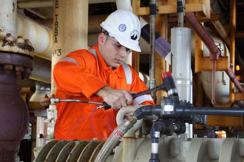
Field testing and vibration troubleshooting are essential to finding the problem root cause in all industries using pumps, compressors, turbines, fans, bearings, gearboxes, motors, generators, and other critical service rotating machinery. A vibration troubleshooting effort may include experimental modal analysis (“impact”) testing to determine system natural frequencies; Motion Magnified Video (VibVue®) and Operating Deflection Shape (ODS) characterization to observe system behavior, response, motion, and deflection under operational loading; pressure pulsation measurements using dynamic pressure transducers or high frequency accelerometers pump cavitation assessment; strain gauge measurements on rotating components (using RF telemetry) or on piping or structures; and continuous monitoring during transient events.
"MSI’s ability to be responsive to this requirement for us is greatly appreciated. Getting the testing completed, the data reviewed and processed, then getting the report generated as rapidly as it has been, is of extraordinary worth.
I would like to also complement [MSI field technicians’] organization, efficiency, dedication and professionalism that went a long way in expediting and smoothing the testing and data gathering process".
Eric Frieze
Field performance testing is occasionally needed to help troubleshoot field problems. All these specialized testing techniques often help support root cause analysis (RCA), such as, repetitive bear failure, crack shaft, or any other chronic failure on rotating machinery.
The problem-solving process may begin with MSI performing more traditional vibration testing or reviewing data provided by the customer. By evaluating the entire system, including foundation, support structures, and piping, and employing supplementary tools such as finite element analysis (FEA) and computational fluid dynamics (CFD), MSI can reliably design solutions for the most challenging problems, even when others have failed.
Watch George D'Entremont, Machine Vibration Analyst, talk about his experience working with Mechanical Solutions.
“If you are experiencing complex mechanical issues, I recommend Mechanical Solutions as a resource to solve those issues.”
George D'Entremont
Machine Vibration Analyst
"Thank you for your commitment in getting this issue resolved. Knowing you, I would not have expected anything else from you and your organization. MSI is truly a class act..."
Martin Simms
Atlantic Equipment Resources
APPLICABLE ACROSS ALL INDUSTRIES
Field-Testing Technologies
MSI VibVue® Motion Magnification
MSI VibVue® Motion Magnification uses high-speed video analysis to easily and rapidly pinpoint the root cause of the vibration or dynamic problems.
Learn More About MSI VibVue® Motion MagnificationExperimental Modal Analysis (Impact Testing or Bump Test)
Determines natural frequencies and vibration mode shapes key to avoiding and/or diagnosing resonance that can cause vibration amplitudes often resulting in machine failure.
Learn More About Experimental Modal Analysis
Strain Gauge Testing
Measures torsional rotordynamic natural frequencies or torque for performance testing, or used to help solve pipe strain problems or investigate increased rotor issues due to torsional resonance.
Learn More About Strain Gauge TestingOperating Deflection Shape (ODS) Characterization
Measures a rotating system’s vibratory response to operational excitation to diagnose problems ranging from imbalance and misalignment, to looseness, soft foot, resonance, and more.
Learn More About Operating Deflection Shape (ODS) CharacterizationContinuous Monitoring
Custom instrumentation for a particular rotating machinery to monitor various operating conditions using MSI’s proprietary software and advanced instrumentation.
Learn More About Continuous MonitoringPressure Pulsation Testing
Intrusively or non-intrusively quantifying dynamic pressure in piping and casings to help diagnose performance, structural and acoustic vibration, and cavitation problems.
Learn More About Pressure Pulsation Testing
How Experimental Modal Analysis (EMA) Works
EMA, also known as Impact Testing, involves mechanically exciting the system under test via impulse, then measuring the resulting vibratory response. The impulse is most commonly achieved by striking the system with an instrumented hammer, while the vibratory response is measured with accelerometers. The size of the instrumented hammer is selected based on the system under test. Smaller systems require lighter hammers, which better excite the higher natural frequencies commonly associated with small or lightweight structures. Large systems, such as industrial turbomachinery, require heavier hammers capable of transferring the energy required to achieve a measurable response.
The resulting vibration ring-downs from several repeated impacts are measured for each response measurement location, with the responses from each strike averaged together to reduce noise in the data. Impacts are commonly applied in all three directions. The response accelerometers are typically placed at many locations around the system under test to create a comprehensive mapping of the vibratory motion. Impact Testing can be performed on both stationary systems and on running systems to capture the effects of the forces and masses associated with operation on the natural frequencies. When performing Impact Testing on operating equipment, MSI’s Time Averaged Pulse (TAP™) technique enables the extraction of natural frequency and mode shape information from the vibration signatures associated with normal operation.
A frequency response function calculated from a modal test. The peaks identify the natural frequencies of the system under test.
How Operating Deflection Shape (ODS) Characterization Works
To measure the operating deflection shape, the system must be run at steady state conditions for an extended period, typically one to several hours depending on the complexity and size of the system. Depending on the type of machinery involved, this often means constant speed, power, flow, pressure, etc.
One accelerometer is placed at a location of known high vibration to serve as the “reference” accelerometer. Triaxial accelerometers–typically up to four at a time–are then placed at strategic locations around the system while the signals are recorded for approximately one minute.
After each recording, each triaxial accelerometer is moved to a new location, while the reference accelerometer remains in place. A new recording is captured and the process is repeated until a comprehensive mapping of the system has been created. Often, measurements are created at tens or even hundreds of locations, with the process expedited by using multiple triaxial accelerometers to reduce the number of recordings.
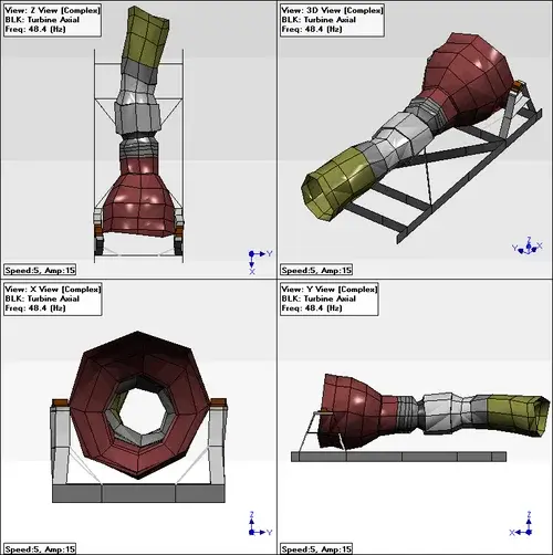
Magnitude spectra and relative phase spectra (relative to the phase of the reference accelerometer) are computed for the entire dataset. The number of spectra is equal to the number of recordings × the number of triaxial accelerometers × 3 directions per accelerometer. These spectra are mapped onto a CAD model of the system and animated at frequencies of interest to characterize the operating deflection shape. For rotating systems, the motion of the shaft can be included using data collected from proximity probes. Imbalance and misalignment can be identified by animating the CAD model using spectra data at 1X and 2X the running speed.
.jpg?width=1037&height=500&name=ODS-Test-Equipment-(1).jpg)
Benefits of Testing and Troubleshooting
All these testing techniques can be used to diagnose vibration problem root causes, then they can be analyzed and resolved.
Knowing natural frequencies and mode shapes enables avoiding or diagnosing resonance causing increased vibration amplitudes leading to fracture, fatigue or other failures.
For rotating machinery, ODS helps to diagnose problems ranging from imbalance and misalignment, to looseness, soft foot, resonance, and more.
Continuous monitoring enables rotating machinery condition monitoring and operational performance optimization for efficiency, production rates, or other characteristics.

REAL-WORLD EXAMPLES AND CASE STUDIES
MSI In Action
Case Study
Solving a Below-Ground VTP Resonance with Specialized Testing and Analysis
Two vertical turbine pumps (VTPs) installed in a nuclear facility were suffering from premature wearing of the line shaft bearings and shaft sleeves, leading to frequent and costly repairs
Case Study
Dramatic Ring-Section Pump Vibration Improvement Using ODS
MSI’s ODS testing suggested modifications for the baseplate of a Boiler Feed Pump that greatly reduced the max vibration amplitude at the outboard bearing housing, solving the problem.
Case Study
Steam Turbine Generator Bearing Lift Oil System Failure Diagnostics
A nuclear power generating station was looking for answers after both main steam turbine generator trains lost their bearing lift oil systems after each experienced the failure of a one inch oil supply pipe.

