A 45 MW steam turbine at a waste-to-energy facility in the Northeast underwent a scheduled repair, at which time the turbine bearings were reworked. After this rework, the turbine periodically experienced very high amplitude shaft vibrations. This phenomenon was associated with either unexpected cold ambient temperatures or with a disrupting event in the plant (e.g. one boiler shutting down) resulting in a sudden shift in turbine load. These events were usually followed by several hours of plant maintenance personnel working frantically to keep the turbine vibrations below the pre-set trip levels. Exceeding these levels would have shut down the turbine, and the plant would have begun consuming electricity (at a penalty rate) rather than producing energy (the primary income for the co-gen facility is from incinerating waste, and not power generation).
The plant had experienced unusually cold weather the evening before MSI engineering consultants arrived on-site to perform specialized turbomachinery vibration troubleshooting testing, which had triggered one of these turbine vibration events. MSI engineers observed the shaft orbits and vibration spectra using the proximity probes which were installed at each bearing location. The spectra of the proximity probe signals were monitored with high frequency resolution (0.06 Hz resolution), and this indicated a strong subsynchronous vibration component which was just below 50% of running speed.
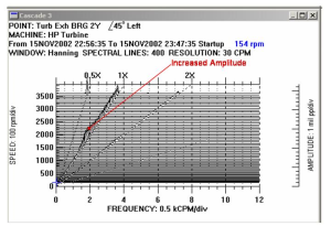
The shaft orbits at the two turbine bearing locations had a secondary loop and did not have stable amplitudes. MSI engineers arrived the second morning to find that the turbine was vibrating in a similar manner due to an emergency shutdown of one of the two boilers as a result of an unacceptable air pressure differential in the boiler. The characteristics of the vibration were identical to the previous day. A key clue concerning root cause was that the proximity probe vibration spectra during normal operation indicated a rotor critical speed at 49% of running speed.
MSI concluded that the vibrations were due to classic rotordynamic instability. The physical explanation of rotordynamic instability is that the whirl of the rotor, driven by the net fluid swirl forces surrounding it (typically at slightly less than 50% of the rotational frequency of the rotor), is at a frequency that matches the rotor natural frequency, causing resonance. In such a case, the rotor no longer responds to the force of swirling pressure fields as soon as those forces are applied, but instead, is delayed by a quarter turn of the rotor’s whirl orbit. The “cross-coupled” (perpendicular to eccentricity) force, which acts in a direction opposite to the rotor’s energy-absorbing damping force, then acts with a 90 degree phase lag, so that it “waits” until the rotor minimum clearance “pinch point” has rotated 90 degrees. Essentially, this means that a slight radial displacement of the rotor will result in forces which act to increase this displacement, until the rotor ultimately makes mechanical contact with the bearing surface. Some call this “negative damping”.
Previous consultants had performed vibration analysis and testing of this turbine and had failed to identify the problem. MSI engineers wanted to perform a coast down test on the turbine to confirm the rotor critical speed at 49% of running speed, but was unable to perform this test as it would have interfered with the plant operation. However, coast down data from a previous consultant was used to very clearly confirm this critical speed. This is a case where another consultant had all the information to solve the problem, but could not put the pieces of the puzzle together.
Several recommendations were made, each of which had a different level of difficulty:
- Control the temperature of the lubricant to maintain a sufficiently low viscosity and reduce the cross-coupled stiffness. This recommendation was very simple to implement and required no hardware changes.
- Change the turbine bearings to break up the fluid swirl. This would require either pressure dam or tilting-pad bearings. This recommendation would require a significant amount of hardware modification including changing the bearings and housings.
- Modify the rotor to shift the rotor critical speed above 50% of running speed. This involves major changes to the rotor, but would eliminate the rotordynamic instability.
