Improving Cost Of Ownership With Vibration Risk Reduction: 2/2
Part 1 case history provides an overview about lowering the risk of vibration problems in new or modified plant designs. It also provides more detail about the specification writing and analysis portion of the risk reduction effort. This Part 2 case history discusses the post-installation vibration verification testing (lower right in Figure 1).
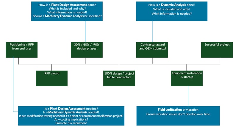
Figure 1. Answers the question “At what point in a project timeline should vibration expertise be used to help reduce risk for a successful new or modified plant design?”
One goal of a field vibration verification test is obvious – confirm the pump, blower or centrifuge systems meet overall vibration criteria as set forth in the specification. Usually ANSI/Hydraulic Institute Standard 9.6.4 is specified for the pump test process and the vibration criteria. ISO 10816 or API can be applicable in the case of pumps or other rotating machinery. AE firms and some end-users will also have their specified requirements.
Another goal of the verification test is described below, with the end result being more reliable equipment operation and reduced operating costs over the life of the plant.
Figure 2 is an example deliverable. It is overall vibration levels at one measurement location in three directions while the pump operates within its acceptable operating region. There will be several measurement locations specified and several speed lines in the case of variable speed equipment.
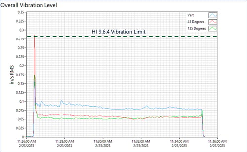
Figure 2. Example overall vibration measurement compared to the HI acceptance criteria at a single location and running speed (measured in three directions). The number of measurement locations is dependent on the pump type.
The specifications should also require that the independent test company provide and analyze Fast Fourier Transform (FFT) vibration plots (“vibration signatures”), which show vibration amplitudes versus vibration frequency. Potential issues such as mis-alignment or imbalance can be identified and corrected before the new or modified plant is turned over to the owner. The time and cost adder is nominal and FFT analysis provides excellent value for reducing vibration risk.
Figure 3 is an example of a delivered FFT with key excitation sources (running speed and vane pass frequency) compared to natural frequencies. Problems such as imbalance, misalignment, and internal rubbing can be identified and eliminated based on the FFT.
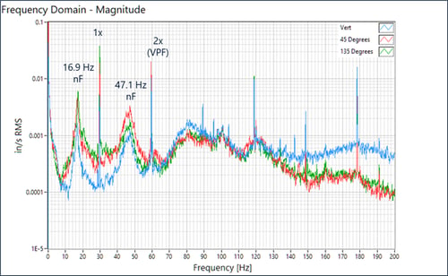
Figure 3. An example FFT comparing vibration magnitude versus frequency indicating a pump with good vibration characteristics and a lower probability of encountering a resonance issue. The experienced pump engineer identified the maximum running speed (1x) and vane pass frequency (2x for a 2 bladed pump). They have also labeled the approximate frequency of the first and second structural natural frequencies.
If lowering the overall cost of ownership is an objective, then an experimental modal analysis (impact test) should also be specified. An impact test allows the pump engineer to predict the future, and help ensure the pump system will operate over the life of the plant without encountering resonant vibration.
Vibration data collected during the verification test can be also used as a baseline or birth certificate for comparison to later data (trending) if a plant is practicing predictive maintenance to lower the cost of ownership.
Figure 4 is a key deliverable from an impact test. It is a Frequency Response Function (FRF) plot, which helps to show the natural frequencies, or vibration modes, of the pump or equipment. FRF plots are evaluated to:
- Confirm that rotating machinery and related piping is not suffering from a structural or acoustic resonance issue.
- Confirm that the specified separation margins between excitation frequencies, such as running speed, and natural frequencies (usually 15%) have been met.
- Evaluate the potential for encountering a damage-causing resonance issue as the pump system ages.
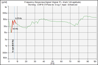
Figure 4. Example Frequency Response Function (FRF) plots based on specialized impact test results. FRFs are used to help an experienced pump engineer differentiate between benign structural natural frequencies versus natural frequencies that could lead to a resonant (high vibration) condition. This is particularly important for variable speed equipment and pumps with a low impeller vane count.
An emerging verification test is the use of Motion Magnification Video (Figure 5). This fairly new technology and product was originally used primarily for troubleshooting. High speed cameras and specialized software exaggerate and slow down the systems motion so potential dynamic problems can be seen and corrected. Displacements as low as 0.1 mil pk-pk at a 10-foot field of view can be identified.
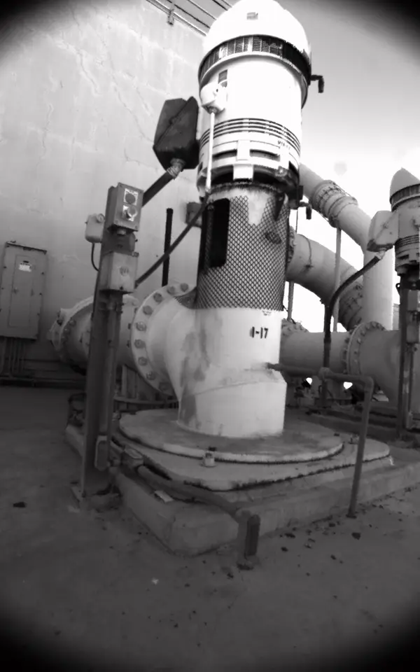
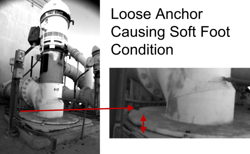 Figure 5. Motion Magnified Video (MMV) is a troubleshooting test method that is emerging measurement tool for vibration verification testing. It is also currently used to test a pump system prior to it being modified. This is motion magnified video of a vertical turbine pump with a soft foot issue due to a loose anchor bolt (see video below).
Implementing the analysis and testing methods by an independent company as discussed in this two-part case history will significantly reduce the risk of vibration issues for the plant owner, contractor, engineer, and manufacturer. Over the long term it will also lower the overall cost of ownership for the plant operator.
.gif?width=600&height=214&name=ezgif.com-video-to-gif(1).gif)
REAL-WORLD EXAMPLES AND CASE STUDIES
MSI In Action
Case Study
Improving Cost of Ownership with Vibration Risk Reduction: 1/2
Focusing on vibration and dynamics issues during the plant design phase of a project pays off with smoother commissioning and lower cost of ownership over the plant’s life.
Case Study
Simulating the Performance of a Spinal Implant
A manufacturer of an innovative spinal implant approached MSI for help in assessing the implant’s structural integrity.
Case Study
Dynamic Analysis of a Street Sweeper for the Manufacturer
Troubleshoot and identify potential opportunities for early bearing failure, MSI performed experimental modal analysis (EMA) and operational deflection shape (ODS) tests on a prototype unit for the manufacturer.

