You know which pieces of equipment come to mind when you hear the term, “Bad Actor.” These machines seem to delight in their status as an outlier, with abnormally low MTBFs (mean time between failures) and higher than average maintenance budget consumption, both in parts and labor, and heartburn medication. According to Heinz Bloch in Pump Wisdom, about 7% of the pump population consumes 60% of the money spent on pump maintenance and repair. This bad behavior is a constant threat to peace and productivity in your plant, and bad actors have hamstrung or even ruined many a career.

To top it off, they really seem to like it that way. Getting them to change is hard, if not seemingly impossible, with typical fixes never quite bringing them around to play nice like the others. To make things even worse, the various internal and external experts you consult in fixing the issues in these bad actors seem to have different opinions on what the problem could be, and even more opinions on what to do to fix the machinery, adding politics, turf wars and egos to the list of associated challenges. No wonder they have such a bad reputation!
Now, imagine on top of all these issues, you were running a Water Treatment plant in the middle of the arid desert region of southern Arizona, USA, where water is a precious commodity. At the City of Chandler’s Pecos Surface Water Treatment Plant, four 100 HP raw water vertical turbine pumps, driven by variable frequency drives (VFDs) running around 900-1200 RPM, were auditioning for bad actor roles with advanced wear on the line shaft bearings, excessive overall vibration, and repetitive failures, including below-ground portions of pump.
This had been a problem for years, since about two months after the acceptance test. Only a nominal design assessment had been performed to anticipate potential resonance issues. Finger-pointing by service and equipment providers had failed to accurately diagnose the issue, never mind resolving it. Chandler had taken several steps to isolate the problem and had attempted some fixes based on recommendations, such as fixing a soft foot issue, but the problem persisted. Because of this, the pressure was on to fix the problem completely.
The Decision
After reviewing the customer’s data and reports from prior consultants, Mechanical Solutions, Inc. (MSI) was confident they could accurately diagnose the problem AND provide an engineered solution based on our experience and previous similar engagements. An important question MSI planned to answer with specialized testing was whether the advanced wear was due to a forced response issue, a resonance issue, or possibly both. Based on the data presented by the customer, it appeared resonance was playing a part, with possible soft foot and foundation looseness contributing.
Regardless of what the problem turned out to be, MSI highlighted that diagnosis is only a way-point on the path to problem resolution. The City of Chandler team understood and appreciated the difference between the “engineered solution” that MSI provides and “trial-and-error” problem-solving. One is potentially dangerous to an engineer’s career, while the other makes them look like heroes. The team at Chandler was more interested in being a hero at this stage of the game.
The Diagnosis
Multiple specialized test methods were employed over two days of testing to ensure the issue was completely understood. The test plan relied on a variety of sensors, including triaxial accelerometers above ground and submerged, multiple sets of proximity probes for shaft vibration, and high-speed video.
The test techniques MSI uses work together for a comprehensive understanding of the machine as a complete system. From this holistic vantage point, MSI is able to rule out possible contributors, and definitively diagnose the specific problems.
For this particular situation, MSI gathered the following information:
- otion magnification data using MSI VibVue® Video Vibration and Motion Magnification, as well as Operating Deflection Shape (ODS) analysis with about 300 measurement points (including underground), to see the overall behavior of the vibration. Both methods indicated excessive motion with distinct mode shapes when operating at 1087 RPM/17 Hz and 1137 RPM/19 Hz.
VibVue® Motion Magnification demonstrated strong perpendicular excitation at 17 Hz while operating the pump at 1017 RPM/17Hz
VibVue® Motion Magnification demonstrated strong parallel excitation at 19 Hz while operating the pump at 1137 RPM/19Hz
An additional view of VibVue® Motion Magnification demonstrating minor perpendicular excitation at 19 Hz while operating the pump at 1137 RPM/19Hz
ODS modeling indicated a "C-shape" bending mode at approximately 19 Hz
- Continuous monitoring of vibration above ground at the top of the motor, at the top of the discharge head, and below ground at the suction bell mounting flange, indicated elevated vibration while running at certain speeds. Specifically, operating at just over 1,000 RPM (~17 Hz) and around 1,150 RPM (~19 Hz) caused higher vibration v in the perpendicular and parallel directions, respectively.
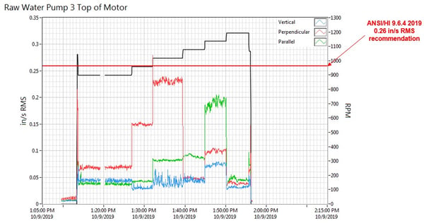
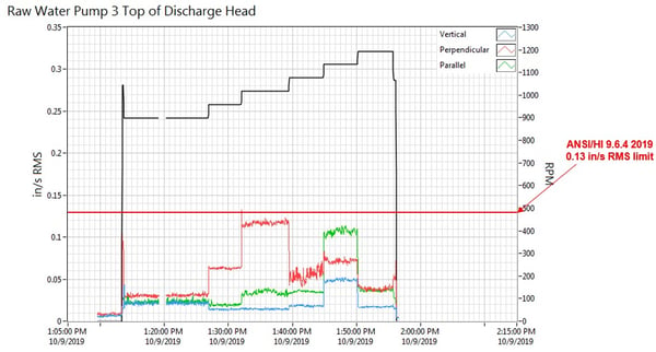
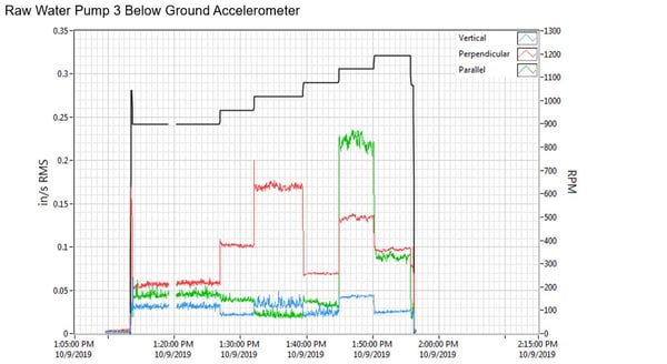
Vibration levels at the top of the motor, the top of the discharge head, and the suction bell mounting flange were elevated in the perpendicular direction at just over 1,000 RPM (~17 Hz), and in the parallel direction at around 1,150 RPM (~19 Hz)
- Experimental modal impact results measured at the top of the motor, the top of the discharge head, and below ground at the suction bell mounting flange, with impacts and measurements in both the parallel and perpendicular directions, relative to the discharge piping.
It is important to note MSI prefers to perform modal testing during operation, since the operation of the machine will typically shift the natural frequencies, potentially into or out of the range of potential excitation. The Frequency Response Function (FRF) plots clearly indicated natural frequencies within the operating range of the pumps, specifically at 19.25 Hz and 23 Hz in the parallel direction, and 17 Hz and 23.75 Hz in the perpendicular direction. The lower frequency mode shape coincided with the pump “C-Shape” mode (depicted below), and the higher frequency mode shape coincided with the above-ground 1st bending mode. When excited by the operating speed of the pumps, these resonance conditions were responsible for the damage done, and lay at the heart of the bad actors.
%20NEW.webp?width=600&height=495&name=VTP%20Below%20Ground%20Nfs%20and%20Mode%20Shapes%20(003)%20NEW.webp) Engineers can understand below-ground mode shapes according to their frequencies
Engineers can understand below-ground mode shapes according to their frequencies

Pump 3 Parallel Impact Parallel Response - Top of Motor

Pump 3 Parallel Impact Parallel Response - Top of Discharge Head

Pump 3 Parallel Impact Parallel Response - Suction Bell

Pump 3 Perpendicular Impact Perpendicular Response - Top of Motor

Pump 3 Perpendicular Impact Perpendicular Response - Top of Discharge Head

Pump 3 Perpendicular Impact Perpendicular Response - Suction Bell Mounting Flange
This information was all clearly and quickly communicated to the customer within just a few weeks following the data collection. The report was easy to understand, written in plain, straightforward language, with only necessary supporting data. And of course, with a definitive diagnosis in hand, the report also included recommendations on how to fix the problem once and for all.
The Solution
For the problem to be resolved, either the exciting frequency (operating speed) needed to change, or the natural frequency needed to change. Instead of altering the process, and possibly causing other issues, the recommendation was to change the structural natural frequency of the pumping system by adjusting the stiffness and/or damping of the system. It is important when shifting problematic natural frequencies to not stumble into others that were inadvertently shifted as well. While the customer was waiting to implement the fix, MSI recommended they “lock out” the problematic frequencies from pump operation to avoid further damage.
MSI recommended Chandler add stiffening ribs to the underground pump column and to the above-ground discharge head, but also recommended that a detailed design should be confirmed with a calibrated Finite Element Analysis (FEA) model. An FEA pump system model, including foundation and discharge piping, was subsequently built and accurately tuned to the field test data.
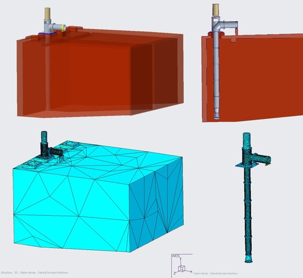
MSI created detailed FEA models using a system-level approach and tuned them to field data
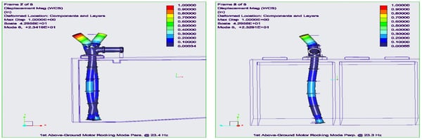
The FEA model confirmed the 1st above-ground motor rocking mode in both the parallel/ 23.4 Hz (left) and perpendicular/ 23.3 Hz (right) directions
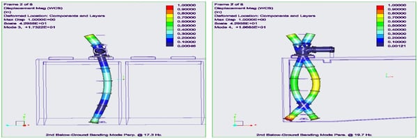
The FEA model confirmed the problematic 2nd below-ground "C" shape bending mode in both the perpendicular/ 17.3 Hz (left) and parallel/ 19.7 Hz (right) directions

With an accurate model to test modifications, MSI determined optimal structural enhancements to shift the problematic natural frequencies sufficiently away from the operating speed range, while not shifting others to become a problem. Specifically, MSI recommended ribs and supplemental bolts with precise dimensions and locations for the discharge head, along with ribs on certain column sections. This was all provided within a few weeks of the customer deciding to proceed with the FEA solution.
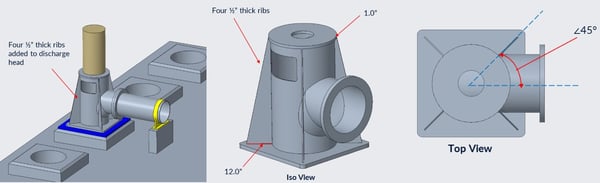
MSI provided a detailed rib design to help stiffen the discharge head
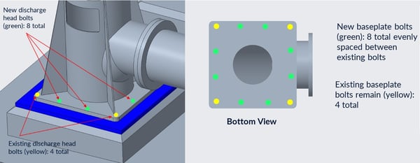
MSI recommended detailed supplemental bolting to help stiffen the discharge head
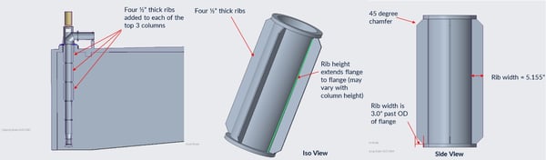
MSI also provided a detailed rib design for specific column segments to further increase the stiffness of the pumping system
Solution Confirmed
After the customer had implemented the recommendations, MSI returned to verify the natural frequencies had shifted as intended, and that the overall vibration levels had been reduced to acceptable levels.
Sure enough, the natural frequencies were safely shifted away from the operating range, with the pump vibration now well below the Hydraulic Institute Standard 9.6.4 Rotodynamic Pumps for Vibration Measurements and Allowable Values. The City of Chandler completely resolved its “bad actor” issues, and the previously troublesome pump transformed into a “model citizen” in a matter of months.
To learn more about our problem solving expertise, check out additional case studies below. If you would like us to help you solve your problem, please Contact Us, and we would be happy to do so.
