Solving Chronic Coupling Failures in a Dredge Pump System Using Torsional Vibration Testing
Summary
Mechanical Solutions (MSI) used torsional rotordynamic vibration analysis, shaft strain gauges, wireless telemetry, vibration monitoring, and VibVue® motion magnification testing to diagnose repeated coupling failures in two 5,000-bhp diesel-engine-driven dredge pumps.
Testing confirmed that torsional resonance—not alignment, structural vibration, or shaft displacement—was causing flexible rubber coupling inserts to fail. The resonance was driven by 1/3× engine speed excitation and 1× pump speed, creating alternating torque loads exceeding ±60% of mean torque.
MSI recommended engine tuning and torsional rotordynamic analysis to reduce resonance risk. Engine tuning ultimately resolved the coupling failure issue, demonstrating how torsional vibration testing can identify the root cause of chronic dredge pump coupling failures.
MSI conducted advanced diagnostics and torsional vibration testing on two diesel engine (5000BHP)-driven dredge pumps (Figure 1) aboard the dredge vessel operating in the northeast USA . The pumps experienced repeated coupling failures during extended operation (Figure 2).
Field testing including the use ofstrain gauges with a telemetry system (Figures 3 and 4) identified that the failure root cause of the flexible rubber coupling inserts is a torsionalresonance in the shafting system excited by:
- 1/3× engine rotational speed (sub-synchronous vibration)
- 1× pump rotational speed
Two dominant torsional natural frequencies were measured between 3.6 and 6.0 Hz, closely aligning with the excitation frequencies generated by the drivetrain.
The resonance caused high alternating torque loads exceeding ±60% of the mean torque, leading to fatigue failure of the flexible rubber coupling inserts.
MSI cost- effectively determined that the following were not contributing to the problem by using Vibration Monitoring, VibVue® video magnification (Figure 5):
-
Structural vibration levels were within acceptable limits
-
Shaft displacement was not excessive
-
Installation or alignment issues including baseplate delamination were not the primary cause
The recommended mitigation strategy includes:
-
- Tuning the engine to see if the subsynchronous excitation source was related to a possible engine tuning issue.
- IF item 1 failed to help perform a Finite Element rotordynamic torsional analysis to evaluate one of the following
- Replacing the flexible rubber couplings with gear-type couplings
- Evaluating engine torsional dampers and 1/3× harmonic excitation
With recommendation 2, the goal would be to increase torsional stiffness in the drivetrain to shift natural frequencies away from excitation sources, significantly reducing the risk of coupling failure.
Spoiler Alert – Tuning the engine resolved the coupling failure issue . Item 2 may still come into play IF the engine-pump system is overly sensitive to mis-tuning.
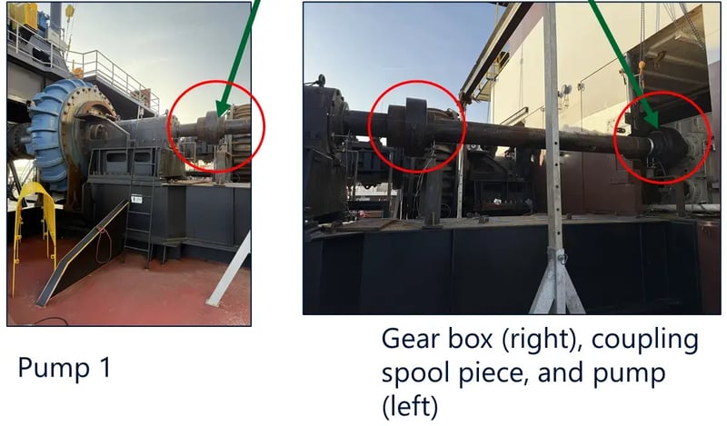
Figure 1. Failed coupling location
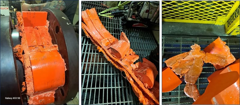
Figure 2. Example of previous coupling failure
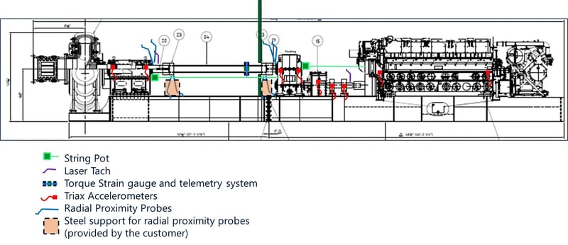
Figure 3. Instrumentation plan is shown above. The results from the strain gauge and telemetry system were very helpful in determining the problem root cause.
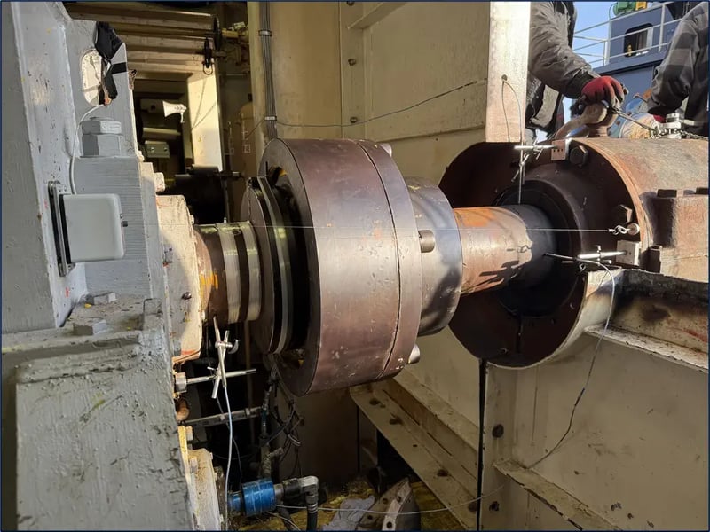
Figure 4. String pot, radial proximity probes, strain gauge and telemetry setup.
Figure 5. MSI’s VibVue® Motion Magnification Video system helped eliminate several other potential problem contributors.
What Causes Chronic Coupling Failures in Dredge Pump Systems?
Coupling failures in large rotating machinery systems often occur when torsional vibration or resonance conditions develop in the drivetrain.
In the dredge system, and in all engine driven applications, the two main excitation sources are:
-
engine speed harmonics (in this case 1/3 engine speed)
-
1× pump rotational speed
These excitations aligned with torsional natural frequencies of the shafting system, creating resonance conditions that amplified alternating torque loads.
When torsional resonance occurs:
- Torque oscillations increase dramatically
- Flexible couplings experience repeated stress cycles
- Rubber inserts fatigue and fail prematurely
Testing revealed alternating torque loads up to ±60% of mean torque, which is significantly higher than normal operating conditions.
What Is Torsional Resonance in Rotating Machinery?
Torsional resonance occurs when a system’s torsional natural frequency aligns with an excitation frequency generated by rotating components such as engines, pumps, or gears.
When resonance occurs:
- Torque oscillations increase dramatically
- Shaft stress increases
- Couplings experience fatigue damage
- Equipment reliability decreases
In this case, MSI measured torsional natural frequencies at approximately:
- Pump 1: 3.8 Hz and 6.0 Hz
- Pump 2: 3.6 Hz and 5.8 Hz
These frequencies closely align with the system excitation frequencies.
How Was the Dredge Pump System Tested?
MSI used a multi-method rotating equipment diagnostics approach to determine the root cause of the coupling failures.
Torsional Vibration Testing
Strain gauges were installed directly on the shafts to measure:
- Mean torque
- Alternating torque
- Torsional response
Data was transmitted using a wireless RF telemetry system during pump operation.
Continuous Vibration Monitoring
Simultaneous vibration measurements were collected from:
-
Engine
- Gearbox
-
Pump bearings
-
Pillow block bearings
- Shaft locations
Experimental Modal Analysis (EMA or Impact) Testing
Impact testing was performed to determine structural natural frequencies of the pump train in:
-
Horizontal direction
-
Vertical direction
-
Axial direction
Operating Deflection Shape (ODS) Analysis
ODS testing allowed engineers to visualize the dynamic motion of the pump system while operating.
Motion Magnification Video (MMV)
High-speed video technology was used to amplify visible motion in the structure, confirming dynamic behavior observed in vibration data.
What Were the Key Findings From the Vibration and Torsional Testing?
The testing and analysis revealed that torsional vibration—not structural vibration—was responsible for the coupling failures.
Key Observations
High Alternating Torque
Pump 1:
- Mean torque: ~66,000 ft-lb
- Alternating torque: ±40,000 ft-lb
- Oscillation: ±60%
Pump 2:
- Mean torque: ~72,000 ft-lb
- Alternating torque: ±40,000 ft-lb
- Oscillation: ±57%
These oscillations occurred even when engine speed remained constant, indicating a dynamic torsional response.
Structural Vibration Levels
Measured vibration remained within acceptable limits:
Engine vibration:
-
- ~0.51 in/s RMS
Pump vibration:
-
- 0.31–0.41 in/s RMS
These values indicate that lateral vibration was not the cause of the failures.
Shaft Displacement
Maximum shaft vibration measured:
- Pump 1: 2 mils peak-to-peak
- Pump 2: 6.5 mils peak-to-peak
These values are acceptable for large industrial pump systems.
Why Did the Flexible Couplings Fail?
The installed flexible rubber couplings had variable torsional stiffness depending on load conditions.
As pump loading changed:
- Rubber stiffness changed
- Natural frequencies shifted
- The system moved in and out of resonance
This dynamic behavior created unpredictable torque amplification, leading to repeated insert failure.
Interestingly, couplings with higher stiffness orange inserts failed faster than yellow inserts, despite their higher torque capacity.
How Can Torsional Resonance in Pump Systems Be Prevented?
MSI recommended increasing drivetrain stiffness to move natural frequencies away from excitation sources.
Recommended Solutions
1. Replace Flexible Rubber Couplings
Use gear-type couplings with higher torsional stiffness.
Benefits:
- Stable stiffness
- Reduced resonance risk
- Improved drivetrain reliability
2. Perform Rotordynamic Finite Element Analysis (FEA)
A full torsional rotordynamic analysis should be conducted to evaluate:
- Coupling stiffness options
- Shaft configurations
- Operating speed ranges
This allows engineers to test multiple scenarios without expensive field trials.
3. Evaluate Engine Torsional Dampers
The engine manufacturer should investigate:
- The cause of the 1/3× engine harmonic
- Proper sizing of torsional dampers
Reducing excitation energy will further mitigate torque oscillations.
What Is the Recommended Safety Margin for Torsional Resonance?
Industry best practice recommends maintaining at least a 10% separation margin between natural frequencies and excitation frequencies based on a properly performed impact test on the installed machinery system.
A 15% margin is recommended when the FEA is completed before the machinery is installed, reducing the risk of post-installation vibration problems.
If the margin is smaller, resonance risk increases significantly.
Frequently Asked Questions
What is Rotordynamics Resonance?
Torsional vibration is the oscillating twisting motion of a rotating shaft caused by fluctuating torque. It commonly occurs in systems with engines, pumps, compressors, and gearboxes.
What causes coupling failures in industrial pumps?
Common causes include:
-
torsional resonance
- misalignment
- excessive torque loads
- poor coupling selection
- Overlap between drivetrain natural frequencies and excitation frequencies
How can torsional vibration be measured?
Torsional vibration is measured using:
-
torsional vibration analyzers
- rotordynamic simulation models
What is the difference between lateral vibration and torsional vibration?
Lateral vibration involves side-to-side shaft movement (and is more common), while torsional vibration involves twisting oscillations along the shaft axis.
Coupling failures are often caused by torsional vibration, even when lateral vibration appears acceptable.
Why are gear couplings better for torsional stiffness?
Gear couplings provide:
- higher torsional stiffness
- stable mechanical properties
- improved torque transmission
This helps shift natural frequencies away from excitation sources. However, gear couplings require periodic maintenance (lubrication).