

Figure 1: One of five engine-driven vertical propeller pumps suffered a line shaft failure after 20+ years of operation – Solution Needed.
Problem Statement (Challenge)
What: Five vertical propeller pumps with right-angle gear speed reducers (Figure 1 left) driven by dual-fuel engines (Figure 1 right) at a Primary Effluent Service Pump Station. Two pumps are needed for normal operation with three more required during peak flow. The engines and pumps are exercised monthly at a minimum.
Where: Southwest USA
Why: After 20+ years of operation, catastrophic line shaft failure of the Unit 3 pump (Figure 2 left). A fabricated shaft was used for a short turnaround repair but the pump again after only five minutes of operation. The Unit 3 pump operated for six weeks after a complete overhaul before two line-shaft couplings failed (Figure 2 right). During disassembly sand was found in all of the bronze bearings.
Status: This case history is based on the testing of Units 1, 2, 4, and 5 pumps with Unit 3 out for a second overhaul. Initial recommendations from MSI are being applied for the second overhaul. Unit 3 will be tested again following its re-installation.
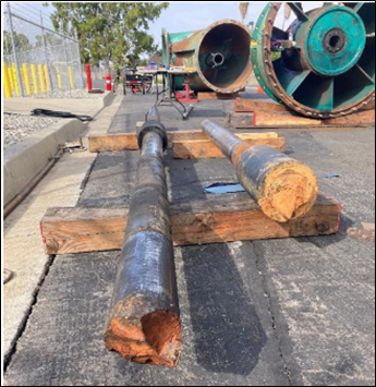
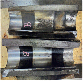
Figure 2: Left – Location of pump line shaft fracture. Right – One of the two broken intermediate line shaft couplings.
Work Performed
Evaluation of operating data, repair history, and a metallurgical lab report; on-site inspection; Torque Strain Gauge Testing, Experimental Modal Analysis (EMA) testing; Condition Monitoring; Operating Deflection Shape (ODS) testing; VibVue® Motion Magnified Video (MMV); and In-office data analysis with reporting that clearly stated solution recommendations.
Background, Results, and Solution
MSI was contacted following the post-overhaul line shaft failure. Excitation of a torsional natural frequency was a suspected problem root cause or contributor based on previous experience with similar failures. However, other issues might also be involved.
The testing performed was a complete pump health assessment including torque measurements. The focus of this case history is on utilizing strain gauges (Figure 3) for practical torque measurements in the field.
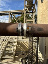
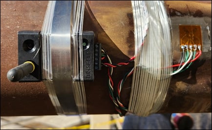
Figure 3: A strain gauge is temporarily glued onto the rotating solid drive shaft between the engine and the gear box with a Radio Frequency (RF) telemetry system to output the torsional strain gauge (torque) signal to MSI’s analyzer with the pump operational. The mean and alternating shear stresses (derived from the mean and alternating torque measured by the strain gauges) were plotted on a Goodman Diagram to assess the operating life of the shafting system.
MSI Results
The root cause of the failures on the Unit 3 pump was due to one and possibly both of the following:
1) Excessive torque oscillation of the shafting system (+/- 1950 ft-lbs. – about 44% of the mean torque) due to excitation of the 2nd torsional natural frequency measured near 42 Hz. The excitation source is two times Vane Pass Frequency (2 x VPF) when the engines operate in the upper speed range ( Figure 4).Extended operation of the engines in this higher speed range coupled with the high-stress concentration at the fillet radii of the line shaft and/or excessive corrosion pitting could raise the alternating shear stresses beyond the Goodman line causing fatigue damage (Figure 5).
2) A below-ground trunnion or C-shaped mode is likely being excited during operation at the upper end of the pump and engine speed range. The offending structural mode shape when resonant will increase the bending moment on the pump line shaft increasing fatigue. Approximate below-ground natural frequencies can be derived even if only collecting above-ground vibration data.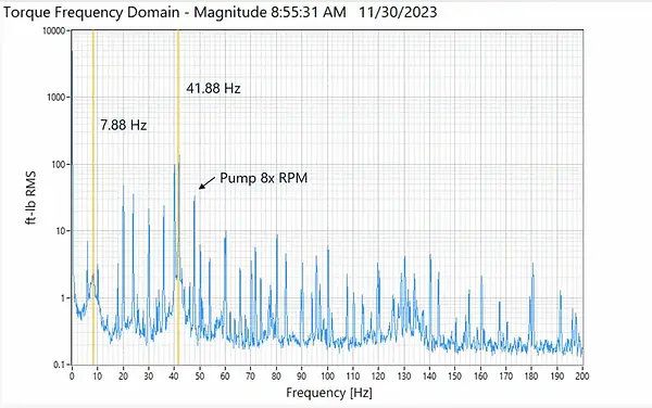
Figure 4: An animation showing driveshaft torque (ft-lbs) versus pump rpm in frequency for one of the four pumps tested when the engine is operated from its minimum to maximum rpm over about 60 minutes. Observe how the Pump 8x speed frequency transitions from above to directly on the 2nd Torsional Frequency at 41.88 Hz (as the engine rpm varies), thereby amplifying the torque oscillation's intensity.
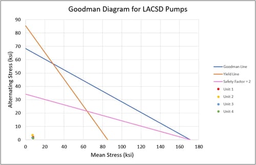
Figure 5: Campbell and Goodman (above) Diagrams are key deliverables from a torque strain gauge test or a torsional rotordynamics analysis. The stress data derived from the strain gauge measurements are plotted on a Goodman diagram. The results fall in the infinite life zone (good) - in theory IF the problematic speeds are avoided to prevent resonance and IF the shaft material complies with the ASTM requirements.
Recommendations and Plan
Near term to reduce the failure risk for the remaining four pumps:
- Lock out the problematic engine speed (1028 rpm for Unit 1 and similar speeds for the other three units) until longer term recommendations can be implemented.
- Verify the alignment between the engine on Pump 2 and the engine side pillow block of the flywheel system.
- Periodically check the water supply to the enclosed line shaft bearings.
Apply during the current Unit 3 overhaul:
- Consider using a more ductile shaft material and measure the shaft material's hardness as part of the overhaul process.
Note: The Goodman Diagram concludes that each shaft will have infinite life in theory IF the problematic speeds are avoided and IF the shaft material complies with the ASTM requirements. In a vertical pump application the line shaft “swings” and bends during normal operation with the bend amplified when there is a resonance issue. Therefore, shaft material ductility is important.
- Pay particular attention to, and document, all alignments and fits between the engine-flywheel-drive shaft-right angle gear-pump head-line shaft assembly during the overhaul and reinstallation of the Unit 3 pump.
- Install submersible accelerometers to the pump suction bell per MSI instructions during reinstallation of the overhauled Unit 3 pump.
Post-overhaul and installation:
- Once the below-ground structure is instrumented with submersible accelerometers, MSI will complete the same test on Unit 3. The below-ground natural frequencies will be more definitively determined. The expectation is that the post-overhaul, Unit 3 will have a clean bill of health and the other four units can be repaired in the future following the recommended process. Alternatively, the most recent Unit 3 test data will be used to provide specific fix recommendations.
