
How FEA Helped Reduce Reciprocating Compressor Piping Vibration
Summary
What Solved the Reciprocating Compressor Piping Vibration Problem?
An independent dynamics analysis of the compressor system specified in the purchase specification and performed before manufacturing and installation could have helped prevent the vibration problem. However, such a risk reduction assessments were not common back when this compressor was specified, purchased, and installed.
MSI engineers with machinery experience used a Finite Element Analysis (FEA) code to evaluate and successfully solve an elevated vibration issue with a reciprocating compressor system (Figures 1 and 2) at a chemical plant. Already available field vibration test data indicated that the discharge piping was vibrating at approximately 1.2 in/s RMS at the compressor’s 1x running speed of about 400 RPM (6.63 Hz). This initially suggested a possible discharge piping resonance problem.
The FEA supported by field experimental modal analysis (impact) testing showed something different than a resonance issue. The impact test determined that the nearest natural frequency of the discharge piping to running speed was an axial natural frequency at 9.13–9.16 Hz (an acceptable 37% separation margin from running speed). That means the high vibration at running speed was not a lightly damped natural frequency being excited by running speed (i.e., resonance). Instead, the likely root cause was compressor discharge pressure pulsation acting on piping supports that were too flexible in the axial direction.
The recommended solution was to increase piping support stiffness by installing the bracing and I-beam boxing depicted in Figures 3 and 4. These modifications accurately predicted a reduction in vibration to well within the acceptance criteria.
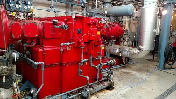
Figure 1: Ammonia reciprocating compressor with a high vibration issue.
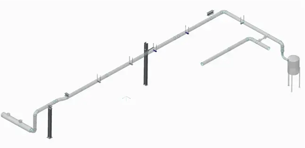
Figure 2: FEA model of the original compressor discharge piping network before modification.
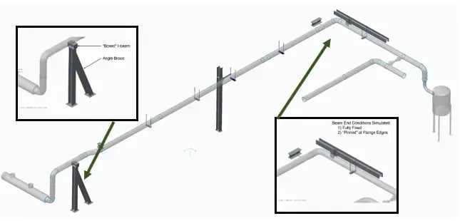
Figure 3: FEA model for the final recommended modifications that successfully reduced reduce piping vibration. An advantage of using FEA is selecting the most practical and effective “intuitive” solution without introducing another vibration problem while avoiding repetitive trial and error modifications.
What Is Reciprocating Compressor Piping Vibration?
Reciprocating compressor piping vibration can occur when dynamic forces (vibration) from compressor operation excite the connected piping system. These forces may come from pressure pulsations, shaking forces, structural flexibility, acoustic issues, or a structural or acoustic natural frequency that aligns with running speed or harmonics.
In this case, the compressor operated at 398 RPM, equal to 6.63 Hz. Field vibration data showed elevated vibration above 1.0 in/s RMS on the overhead discharge piping. Because the vibration occurred at 1x running speed, resonance was initially suspected. However, an FEA model properly calibrated with Experimental Modal Analysis (impact) testing showed that the dominant natural frequency mode was to far away from running speed to cause resonance (a good thing).
Was the Piping Vibration Caused by Resonance?
No. The vibration was not caused by resonance at the 1x running speed.
Experimental modal analysis (impact) testing measured the axial natural frequency at approximately 9.13 Hz, or 548 CPM. After the FEA model was refined with additional support details, insulation mass, and sheet metal covering mass, the FEA model matched the field test data. This close match gave confidence that the FEA model represented the actual piping behavior.
Because 9.13–9.16 Hz is well above the 6.63 Hz operating frequency, the system had plenty of separation margin from the 1x running speed. Therefore, the elevated vibration was better explained as a forced response to compressor discharge pulsation acting on a flexible piping system.
How Did FEA Identify the Root Cause?
FEA allowed the engineering team to compare the original piping configuration with several proposed support modifications. The model included the compressor piping, piping supports, discharge header, and oil trap. The analysis also accounted for added mass from entrapped gas, insulation, sheet metal covers, flanges, and valves.
The original unmodified model predicted an axial natural frequency of 9.16 Hz. The forced response analysis then used an oscillating excitation pressure equal to 5% of the approximately 215 psi discharge pressure. This produced a calculated excitation force of about 850 lbf in the axial direction.
The forced response predicted approximately 1.19 in/s RMS at 6.63 Hz, closely matching the field vibration measurement of about 1.2 in/s RMS. This correlation showed that the model could reliably evaluate proposed modifications.
Why Was the Original Piping Support Too Flexible?
The analysis showed that the piping was flexible in the direction along the major axis of the piping. This flexibility allowed discharge pressure pulsations to create excessive vibration at the running speed even though the piping was not resonating.
The FEA also showed that the I-beam mounted at the top of the first vertical piping support could flex about its web, creating hinge-like flexibility. This reduced the effectiveness of the support and allowed the piping to move more than desired under pulsation forces.
Which Piping Support Modification Was Recommended?
The recommended modification combined three changes (see Figure 3):
- First, install the brace design originally proposed prior to any test or analysis work by MSI.
- Second, add MSI’s proposed angle brace at the first vertical piping support.
- Third, box in the I-beam at the top of the first vertical support to reduce hinge-like flexibility about the I-beam web.
This combined approach successfully predicted the greatest vibration reduction because it increased axial stiffness and reduced support flexibility at a critical location.
How Much Did the Recommended Modification Reduce Vibration?
The unmodified piping was predicted to vibrate at approximately 1.19 in/s RMS at 6.63 Hz. With the recommended fully fixed modification—the originally planned brace, added angle brace, and boxed I-beam—the predicted vibration dropped to approximately 0.15 in/s RMS at 6.63 Hz.
That is a potential reduction of nearly eight times compared with the unmodified condition. Even with less-than-perfect installation, the report predicted the vibration could remain around 0.3 in/s RMS, which is significantly lower than the original condition.
The modification also shifted the axial natural frequency upward. The unmodified axial natural frequency was approximately 9.16 Hz. The most robust fully fixed modification predicted a shifted natural frequency of approximately 18.9 Hz.
Why Is FEA Useful for Machinery and Piping Vibration Troubleshooting?
FEA is useful for machinery and piping vibration troubleshooting because it helps determine whether vibration is caused by resonance, insufficient stiffness, pressure pulsation, or another dynamic force. When calibrated with field data, FEA can simulate proposed modifications before fabrication and installation.
In this case, FEA prevented the team from treating the problem as a simple 1x resonance issue. Instead, the analysis showed that increasing support stiffness was the most effective way to reduce vibration.
What Follow-Up Testing Was Recommended?
After modifications, the piping should be retested to confirm that vibration amplitudes have improved. Repeat Experimental Modal Analysis (impact) testing can also verify whether the axial natural frequency shifted as expected. The report also recommended considering a discharge pressure transducer to measure dynamic pressure pulsation levels and frequency content.
Frequently Asked Questions
What caused the compressor piping vibration?
The vibration was most likely caused by compressor discharge pressure pulsations acting on piping supports that were too flexible in the axial direction.
Was the vibration caused by resonance?
No. Modal testing found the axial natural frequency at approximately 9.13 Hz, while the compressor operated at 6.63 Hz. The FEA predicted a similar unmodified natural
frequency of 9.16 Hz.
How much vibration was measured before modification?
The piping vibration was approximately 1.2 in/s RMS at the 6.63 Hz 1x operating speed.
What was the best piping vibration fix?
The best modification was to install the originally planned brace, add an angle brace at the first vertical piping support, and box in the I-beam at the top of that support (see Figure 3).
How much vibration reduction was predicted?
The recommended modification was predicted to reduce vibration at 6.63 Hz from about 1.2 in/s RMS to as low as 0.15 in/s RMS, depending on installation quality.
Why should piping be tested after modification?
Post-modification can be used to confirm that the vibration amplitude has improved and to verify that the support changes shifted the natural frequency as predicted.