Acoustic Resonance Leading to Destructive Vibration At A Nuclear Power
A nuclear power plant was experiencing chronic reliability issues in its 4 kV switchgear cabinets. The cabinets showed abnormal vibration and intermittent equipment failures. Surprisingly, direct vibration measurements on the switchgear room floor showed very low vibration amplitude at the frequency associated with the turbine generator mounted on the deck above, indicating the source of excitation was not structural transmission through the floor (Figure 1).
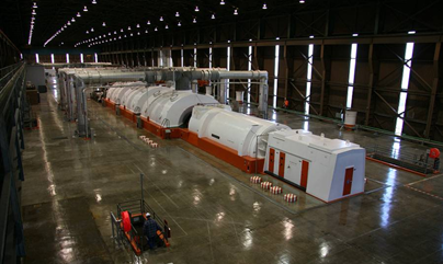
Figure 1. Top - Shows a typical main turbine deck. Bottom – freeze frame of an ODS animation with the periodically failing switchgear one floor below.
Observed Symptoms and Initial Investigation
MSI engineers felt a rhythmic “throbbing” sensation throughout the switchgear area, following a distinct spatial pattern. To diagnose the problem, the team built Operating Deflection Shape (ODS) animations over several days, combining:
- Hundreds of accelerometer measurements on the turbine deck, generator exciter, and switchgear cabinets
- Three-dimensional sound pressure level (SPL) data at hundreds of locations in and around the switchgear room
- Phase-synchronized vibration and acoustic data tied to a common reference point on the generator exciter
This enabled high-fidelity playback animations showing relative motion, amplitude, and phasing across both structures and air volumes (Figure 2).
Figure 2. The exciter was exciting more than the generator! It was "drumming" the floor at 30Hz, with the deck responding with a "rug-flapping" mode.
Key Finding: The Exciter Was “Drumming” the Building at 30 Hz
The animations revealed a critical insight:
The generator exciter was acting like a vibration shaker, drumming the turbine deck at 30 Hz, exciting a large-scale “rug-flapping” structural mode in the deck.
The deck’s motion then energized a 30 Hz acoustic room mode (Figure 3) within the switchgear area. As the acoustic pressure wave expanded and contracted at these antinodes, the switchgear cabinet panels pulsed in and out, amplifying local vibration and damaging internal components such as bearings.
 Figure 3. The turbine deck drove an acoustic mode of the major portion of the switchgear floor- In turn, the switchgear cabinet wall panels pulsed in and out in concert with the acoustic pressure pulsation next to the cabinet, the acoustic pulsation and cabinet response all occurring at 30 Hz.
This multi-physics interaction created a chain reaction:
- Exciter rocking motion at 30 Hz
- → Turbine deck resonance excited
- → Switchgear room acoustic resonance amplified
- → Switchgear cabinet panel resonance triggered
- → Damaging vibration and reliability failures
Modal and ODS Testing Confirm the Resonance Chain
MSI performed detailed Operating Deflection Shape (ODS) testing and impact modal testing on the exciter, turbine deck, and switchgear panels using the TAP™ Time-Averaged Pulse method. All testing was conducted safely while the plant remained online.
Results confirmed that the following all had lightly damped natural frequencies close to 30Hz:
- The exciter (structural mode),
- The turbine deck (structural mode),
- The switchgear room (acoustic mode),
- Multiple switchgear cabinet panels (structural)
This alignment of mechanical and acoustic resonances created a coupled structural-acoustic feedback system.
What Changed?
The switch gear cabinet failure issues started well-after the plant had already been operating for many years.
The exciter’s ODS showed a back-and-forth rocking motion caused by a “soft” or loosened foot (Figure 4), which over time had lowered its natural frequency into the 30 Hz range and triggered the resonance cascade (a fairly common aging plant issue).
Figure 4. The culprit – ODS animation of the rocking motion of the excitor at 30 Hz. An ODS animation is constructed using field measured vibration test data not vibration predictions from a Finite Element Analysis (FEA)
Root Cause and Corrective Action
The root cause was a combined structural–acoustic resonance initiated by the exciter. A loosened structural foot had shifted its natural frequency into alignment with the 30 Hz excitation.
MSI implemented an in-service structural bypass to stiffen the exciter and shift its natural frequency away from the 30 Hz resonance. This mitigation:
- Dramatically reduced excitation at the source
- Lowered vibration throughout the switchgear area
- Eliminated damaging cabinet vibration
- Avoided an unplanned shutdown
- Saved the facility millions of dollars in lost revenue
FAQ: Resonant Acoustics and Switchgear Vibration in Nuclear Power Facilities
1. What caused the destructive vibration in the 4 kV switchgear?
The destructive vibration was caused by a combined structural–acoustic resonance at 30 Hz. A loosened foot on the generator exciter shifted its natural frequency into alignment with the turbine deck and switchgear room acoustic modes, triggering a chain reaction that excited the switchgear panel resonances.
2. Are other nuclear power plants susceptible to a similar issue?
Yes. MSI encountered and solved a similar issue at another plant except it was cable trays mounted to the ceiling that were vibrating excessively.
3. Why didn’t floor vibration measurements show the problem?
The switchgear floor itself showed low vibration amplitude because the primary transmission path was airborne acoustic energy, not structural vibration. The turbine deck’s “rug-flapping” motion drove a 30 Hz acoustic room mode, which excited the switchgear cabinet panels directly.
4. How did MSI identify the resonance pathway?
MSI combined Operating Deflection Shape (ODS) testing, three-dimensional acoustic mapping, and impact modal testing using the TAP™ time-averaged pulse method. This approach revealed synchronized vibration and acoustic phasing across the exciter, turbine deck, air volume, and switchgear panels.
5. What is a 30 Hz acoustic room mode?
A 30 Hz acoustic room mode is a natural standing-wave frequency in an enclosed space. At this frequency, air pressure oscillates between high and low at fixed points (antinodes), producing strong acoustic forces that can excite flexible surfaces like switchgear cabinet panels.
6. What role did the generator exciter play?
The generator exciter acted as an unintended vibration shaker, “drumming” the turbine deck at 30 Hz. Its rocking motion—caused by a softened support foot—generated sufficient mechanical energy to excite the entire structural-acoustic chain.
7. How was the vibration problem ultimately resolved?
The root cause was addressed by implementing an in-service structural bypass on the exciter to stiffen the loosened foot. This detuned its natural frequency away from 30 Hz, cutting off the source of excitation and eliminating the damaging vibration in the switchgear cabinets.
8. Why was modal testing performed while equipment was running?
Conducting modal testing during operation ensured that the results reflected actual in-service boundary conditions, particularly for lightly damped structures. MSI’s low-energy TAP™ method allowed safe testing without risk of tripping or damaging equipment.
9. Could this issue have caused a forced plant shutdown?
Yes. Continued vibration would have led to progressive switchgear degradation, increasing the risk of a forced outage. By diagnosing the issue online and implementing a corrective structural fix, the plant avoided an unplanned shutdown and saved millions in revenue.
10. Are similar resonance problems common in power plants?
Multi-physics resonance problems are not common, but when they occur, they are often difficult to diagnose because they involve interactions between mechanical structures, acoustic fields, and equipment dynamics. Facilities with large rotating machinery and enclosed electrical rooms are more susceptible.
11. What are early warning signs of acoustic–structural resonance?
Typical indicators include:
- Rhythmic “throbbing” or pulsing sensations
- Low-frequency hums (20–50 Hz)
- Intermittent switchgear panel vibration
- Unexplained changes in equipment reliability
- Vibration levels that do not match floor readings
Conclusion
This case demonstrates how multi-physics resonance—structural, acoustic, and mechanical—can combine to produce severe vibration problems in critical electrical equipment. Only comprehensive ODS testing, SPL mapping, and impact modal testing revealed the full resonance pathway. With the root cause identified, a targeted mechanical correction restored reliability and prevented premature plant shutdown.
