
Compressor Vibration and Pressure Pulsation Testing
Summary
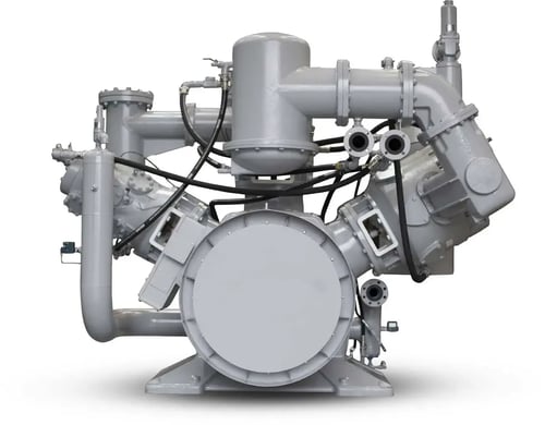
A vibration and pulsation pressure test was performed on a triplex reciprocating compressorused in an air separation plant providing nitrogen to a nearby steel mill. The compressor’s high vibration and noise were symptoms of a reliability problem.
The investigation identified that excessive system vibration was caused by high compressor discharge pressure pulsations, exceeding specification limits, rather than system-wide structural or acoustic resonance.
Key Findings:
• Dominant pulsation frequency: 20 Hz (2x running speed harmonic)
• Secondary harmonics: 10 Hz, 30 Hz, 40 Hz
• Pressure pulsation levels reached 12–20 psi peak-to-peak, exceeding the end-user’s 2% of mean discharge pressure specification (i.e., 8.2 psi peak to peak)
• Limited acoustic resonance observed (no dominant amplification)
• Local structural resonance at 20 Hz in discharge bottle was a minor issue
Root Cause:
The vibration was caused by excessive compressor-generated pressure pulsations transmitted through inadequately attenuated discharge bottle, not piping resonance amplification.
Recommended Solution:
Install an acoustically designed larger discharge bottle or add a second bottle with a choke tube between it and the original bottle.
What Causes Vibration in Reciprocating Compressors?
Reciprocating compressor vibration is typically caused by:
• High-pressure pulsations from compression cycles
• Running speed harmonic excitation (10–40 Hz range in this case)
• Inadequate discharge bottle sizing or design
• Local structural resonance in piping or vessels
In this case, pulsation magnitude—not resonance—was the dominant issue.
How Was the Compressor Vibration and Pulsation Diagnosed?
What testing methods were used in this analysis?
The following field testing tools and methods were used:
• Startup, shutdown, and steady-state operational testing while monitoring vibration, using accelerometers, and dynamic pressure throughout the system.
• Dynamic pressure transducers in the piping measured the problem-causing discharge pressure pulsations.
• Experimental Modal Analysis (impact) testing and the resultant Frequency Response Function (FRF) plots to determine that structural resonance was not a major contributor to the problem.
• Logarithmic spectral analysis of pressure pulsations that eliminated acoustic resonance as the problem root cause or a problem-contributor.
Why is Experimental Modal Analysis (impact) testing important in compressor diagnostics?
Modal testing identifies:
• Natural frequencies and damping of machinery, piping, and vessels
• Potential resonance zones
• Structural response to excitation forces
What Are the Main Pressure Pulsation Frequencies in Reciprocating Compressors?
Which frequencies dominated the system response?
Key pulsation frequencies included:
• 20 Hz (Primary): Dominant system excitation and vibration source
• 10 Hz: Fundamental running speed harmonic
• 30–40 Hz: Higher-order harmonics and localized responses
Why are compressor harmonics important?
Harmonics determine how compressor-generated pulsations interact with:
• Piping stiffness
• Vessel volumes
• System impedance characteristics
Was Acoustic or Structural Resonance the Main Problem?
Is acoustic resonance responsible for vibration in this system?
No. The system showed:
• No significant broadband “noise floor” amplification
• No quarter-wave or half-wave acoustic resonance families
• Only localized structural resonance effects
Key Insight:
This was a non-resonant, pulsation-driven vibration system, not an acoustically amplified one.
Why Was System Pressure Pulsation Exceeding The Specification?
What caused excessive pulsation levels?
The primary causes were:
• Insufficient discharge bottle attenuation capacity
• High inherent compressor flow pulsation
• Ineffective orifice-based damping
How Can Reciprocating Compressor Pulsation Be Reduced?
What are the best engineering solutions?
Recommended mitigation strategies:
• Step 1 – Determine if the problem root cause is likely a structural or acoustic resonance or a high force non-resonance problem
• Install a larger discharge accumulator bottle
• Add a second bottle with choke tube (acoustic filter system)
• Remove restrictive discharge orifice plate
• Optimize system based on API 618 standards
Why is a choke-tube bottle system effective?
It creates an acoustic impedance mismatch that:
• Attenuates flow oscillations
• Reduces transmitted pressure pulsation
• Maintains mean flow efficiency
Should Structural Resonances Be Detuned?
Do structural resonances drive the vibration problem?
Only locally. Structural resonance was observed at ~20 Hz but:
• Did not dominate system-wide vibration
• Did not amplify pressure pulsations significantly
Recommendation:
• Improve support at discharge bottle base
• Shift local resonance away from 20 Hz harmonic region
Frequently Asked Questions
What is the main cause of vibration in reciprocating compressors?
High-pressure pulsations generated by compressor operation interacting with system impedance.
What is compressor pulsation in simple terms?
It is the cyclic variation in pressure caused by piston motion during compression.
How do you reduce compressor pulsation?
By using properly designed discharge bottles and acoustic filters such as choke-tube systems.
What is API 618 in compressor design?
It is the industry standard for controlling pressure pulsation and vibration in reciprocating compressors.
Can orifice plates reduce vibration effectively?
They reduce pulsation but often at the cost of efficiency and are not optimal long-term solutions.