Root Cause Analysis and Vibration Mitigation for a Nuclear Power Plant
What Caused the Steam Turbine Generator Lift Oil System Failure?
A nuclear power generating station experienced repeated failures of the main steam turbine generator bearing lift oil systems on both Unit 1 and Unit 2. In each case, a one-inch oil supply pipe failed, resulting in the loss of bearing lift oil.
Because lift oil systems are critical for protecting turbine-generator bearings during startup and coast down, these failures posed a significant reliability and safety risk. Temporary corrective actions implemented by the plant introduced additional hazards and did not address the underlying cause.
Mechanical Solutions, Inc. (MSI) was engaged to identify the root cause of the failures and develop a permanent engineering solution to prevent recurrence.
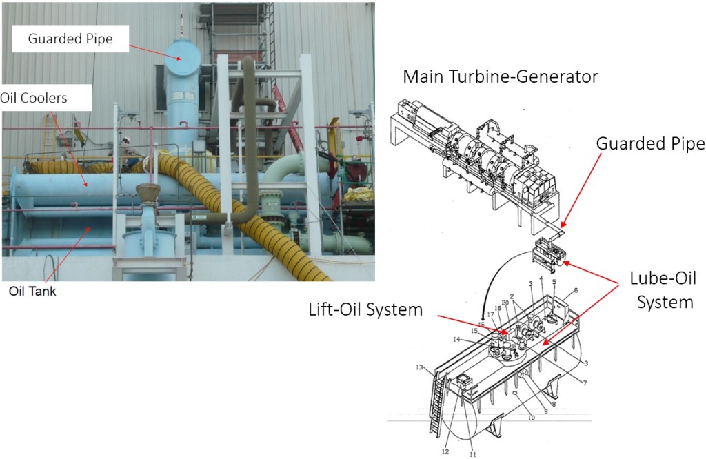 Picture and isometric drawing views of the bearing lift oil system investigated.
What Equipment and Systems Were Involved?
- Machine Type: Main Steam Turbine Generator
- Subsystem: Bearing Lift Oil System Pump Discharge Piping
- Industry: Nuclear Power Generation
- Location: Texas, USA
This case study focused specifically on the vertical lift oil discharge piping inside a guarded pipe section within the oil tank.
Why Was the Lift Oil System Failure a Serious Concern?
The repeated loss of lift oil created the risk of:
- Unexpected turbine bearing damage
- Forced outages and increased maintenance costs
Without a permanent fix, continued operation could have led to catastrophic bearing failure during a coast down event.
How Did MSI Investigate the Lift Oil Piping Failures?
To fully characterize the dynamic behavior of the lift oil system piping, MSI performed a combination of field testing and advanced analytical modeling, including:
- Experimental Modal Analysis (EMA) to identify structural natural frequencies
- Operating Deflection Shape (ODS) analysis to observe piping vibration during operation
- Condition monitoring to assess vibration severity and repeatability
- Finite Element Analysis (FEA) to simulate piping structural response and evaluate corrective modifications
This integrated approach allowed MSI to correlate measured vibration behavior with analytical predictions.
What Was the Root Cause of the Repeated Pipe Failures?
Root Cause:
The failures were caused by resonance between the lift oil piping’s acoustic and structural natural frequencies and the pump’s excitation forces.
More specifically:
The acoustic natural frequency of the oil column inside the vertical pipe and The structural natural frequency of the guarded pipe section were excited by the 2x vane passing frequency (VPF) of the pump. This resonance condition resulted in excessive vibration stresses, ultimately leading to repeated pipe cracking and failure.
What Engineering Solution Prevented Future Failures?
MSI developed a targeted vibration mitigation strategy to eliminate resonance without introducing new safety risks.
Key Engineering Modifications:
- Manual acoustic calculations were used to estimate the required change in pipe length to shift the acoustic natural frequency away from the excitation range.
- Finite Element Analysis (FEA) determined the optimal mass addition to a pipe “U” section to shift the structural natural frequency.
- The combined modifications successfully moved the piping natural frequency outside the 2× VPF range.
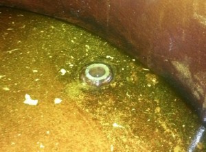 Image of a failure at the bottom of the guarded pipe.
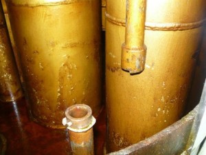
Image of a failure at a joint 3 feet from the bottom of the guarded pipe.
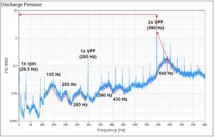
Dynamic Pressure Transducer FFT.
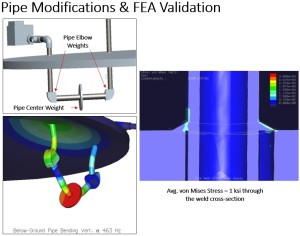
Images of Finite Element Analysis.
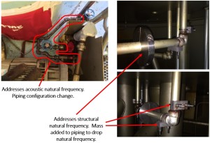
Piping modifications implemented.
What Were the Results and Operational Benefits?
Results and Impact:
- Eliminated resonance-driven piping failures
- Restored reliable operation of the lift oil system
- Avoided the need for flexible piping routed outside the protective guard pipe, which posed safety concerns
- Reduced the risk of turbine bearing damage during startup and coast down
- Improved long-term reliability of a safety-critical system
The permanent solution allowed the plant to maintain safe, compliant, and reliable operation without compromising personnel safety.
Frequently Asked Questions (FAQ)
What is a turbine generator lift oil system?
A lift oil system supplies high-pressure oil to turbine bearings during startup and shutdown, reducing metal-to-metal contact and preventing bearing damage.
Why is the vane passing frequency important in pump vibration analysis?
Vane passing frequency (VPF) is a primary excitation source in centrifugal pumps. If system's natural frequencies coincide with VPF or its harmonics, resonance and high vibration can occur.
How does acoustic resonance affect oil piping?
Acoustic resonance occurs when pressure waves in the oil column amplify vibration, increasing dynamic stresses on piping and potentially leading to fatigue failure.
Why use both field testing and FEA?
Field testing (EMA and ODS) identifies real-world dynamic behavior, while FEA allows engineers to evaluate design changes and confirm frequency shifts before implementation avoiding expensive trial-and-error approach.
Can similar failures occur in non-nuclear facilities?
Yes. Any rotating machinery system with pumps, piping, and confined fluid columns can experience similar resonance issues if natural frequencies align with excitation forces.
