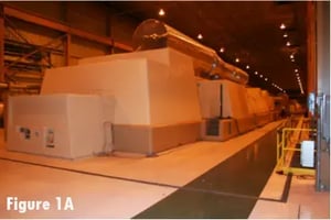
Figure 1: An 800MW steam turbine generator with high vibration and bearing failure issue. Following a period of unsuccessful trial-and-error testing, MSI was contracted by the Plant owner to use specialized vibration testing and experience to determine the problem's root cause(s) and to recommend a practical and successful solution.
Problem Statement (Challenge)
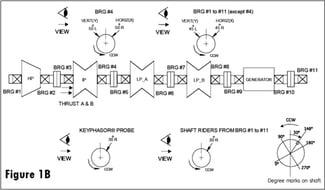
What: 800MW Stream Turbine Generator (Figure 1A and 1B)
Where: Southwest USA
Why: Repetitive failed start-ups (at low power output) with high vibration amplitude and bearing failure
Work Performed
Experimental Modal Analysis (EMA), Condition Monitoring, Operating Deflection Shape (ODS). Work performed in 2010. Today, VibVue® (Figure 2) and TrakVue® (Figure 3) testing tools would have also been utilized to help make the onsite testing more efficient.
Figure 2: Today VibVue® Motion Magnified Video (MMV) would have been used with more traditional vibration test methods to optimize the time onsite and to better discuss the results and recommendations with the plant owner decision-makers. The above is from a recent steam turbine generator project showing bearing vibration at running speed. MSI uses, sells, and supports VibVue®.
Figure 3: Today TrakVue® would have been used to more quickly identify a problem root cause involving some level of misalignment or thermal growth. The above is showing growth in mils versus time at several monitor locations using high-speed cameras. MSI uses, sells, and supports TrakVue®.
Background, Results, and Solution
Before MSI's involvement in January and following a significant outage, the T9 (Generator Inboard Bearing) tripped on high vibration at 200MW during start-up. The unit was inspected, and the required generator stator and rotor repairs were performed. In June, vibration at the T9 generator bearing increased at low load (200MW to 250MW). In October, after a boiler outage and during start-up, the unit tripped several times due to high T9 bearing vibration. Physical inspection led to repairs to the T7 and T8 (LP Turbine) and T10 (Generator Outboard Bearing). MSI’s involvement began in February, 13 months following the initial problems.
MSI Results
MSI’s Experimental Modal Analysis (EMA) or impact test and ODS test demonstrated that the root cause for the generator bearing issue during start-up and low-load operation was an excessive looseness and “soft foot”: 1) between the southeast foot and the concrete floor, 2) between the northeast and northwest support bracket, and 3) at the generator casing (looseness at the connecting bolts).
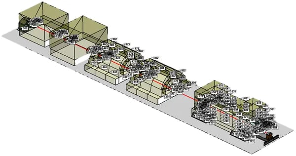
Figure 4: Operating Deflection Shape (ODS) testing is started by recording accelerometer measurements at many locations/directions (in this case, about 1300 measurement locations/directions over a few hours).
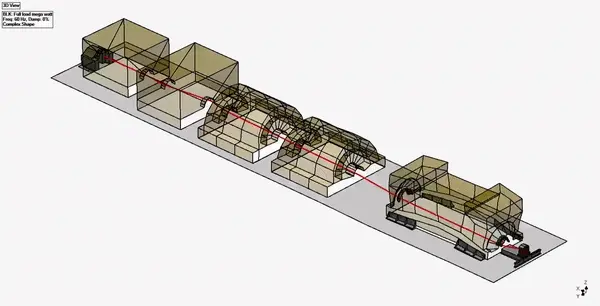
Figure 5: Animation - Software overlays the vibration data onto a 3D model and animates it (exaggerated but to scale). ODS animations are used to find and evaluate looseness, excessive deflection, cracks, and delamination, and to help identify natural frequency excitation issues (i.e., resonance).
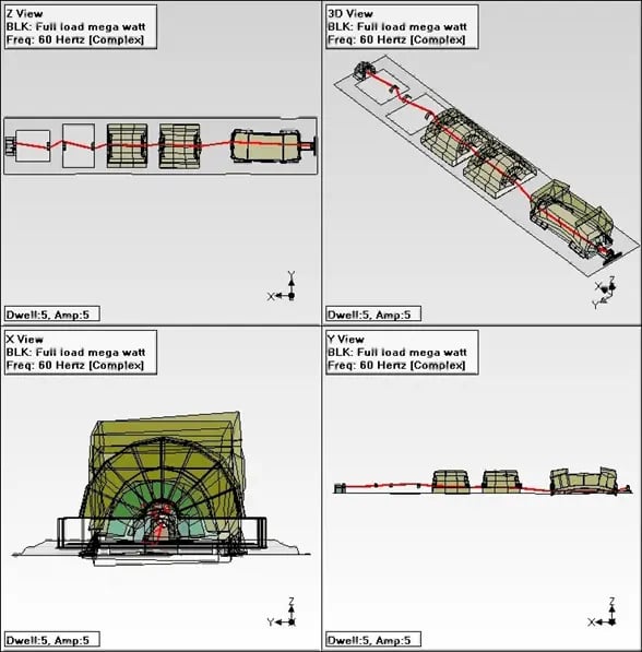
Figure 6: Still frame of an ODS animation in quad view. In this case, the high vertical motion of the generator structure driven by its rotor and the excessive misalignment between the HP and IP turbines (crank-like motion) is shown.
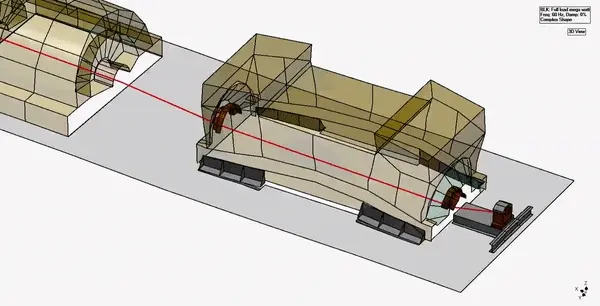
Figure 7: Zoomed-In Animation - Note the high vertical “U” shape motion of the generator structure driven by its rotor motion (Figure 8) and amplified by the soft foot at the South-East support and separation between the casing and at the North-East support. MSI also analyzed more typical FFT spectra and orbit plots to help determine the problem's root cause.
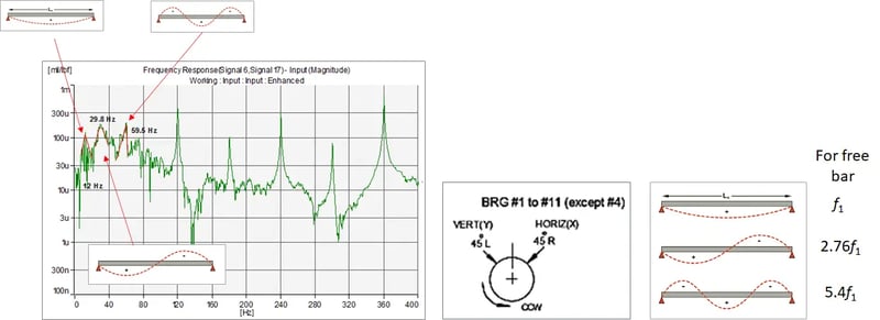
Figure 8: Interpreting the Impact or Experimental Modal Analysis test results. Frequency response function (FRF) plot after impacting the generator rotor at the inboard end (LPB side or T9 X direction). Red lines indicate the rotor natural frequencies (curve-fitting) at 12 Hz, 29.8 Hz and 59.5 Hz indicative of the 1st, 2nd, and 3rd bending modes, respectively. Note that the amplitude is in mils pk-pk. The excitation source for the structural resonance problem at part load excitation was the 59.5 Hz rotor mode.
This looseness excited the 3rd bending mode of the generator rotor (rotor “W” shape mode shown in Figure 8, which amplified a “U” shaped bending mode of the generator structure. All high vibrations were at the generator's running speed (30 Hz).
Why only at part-load? The 3rd bending mode of the generator rotor was particularly sensitive to rotor imbalance. The excitation forcing function was dominant at the low load where the generator rotor residual imbalance present was at its highest due to the uneven transient thermal temperature distribution across the rotor. However, once the rotor reached its full load (800 MW), a uniform temperature across the rotor straightened out the rotor, reducing the residual imbalance excitation forcing function at 1x rpm and, therefore, the subject vibration.
Today, VibVue® Motion Magnification Video and TrakVue® would have been used earlier in the test process, followed by a more focused ODS and EMA impact testing and a shorter onsite test time. (Figures 1 and 2)
The Solution
Tightening the generator support structure bolts made an immediate and significant improvement in bearing vibration during start-up (without causing other issues). However, this may only be a temporary fix. For a future outage, MSI recommended repairing the concrete in the southeast floor area and the inboard generator support area to avoid permanent separation/damage. There was also a need to improve the alignment between the HP and IP turbines, as shown in the ODS animations.
