Overview
A nuclear power plant experienced unusually high vibration levels in their new, modern replacement feed water pumps (Figure 1). The pumps showed 1× RPM vibration at the drive end (DE), step changes in vibration over time, and alignment inconsistencies before and after shutdowns.
The plant needed an independent engineering assessment to determine if the pumps could continue operating safely or if an unplanned shutdown was necessary.
Problem Statement
Machine Type: Single-Stage, Double-Suction Feed Water Pump
Location: Midwest, USA
Industry: Nuclear Power Generation
Challenges Identified:
- High 1x RPM vibration at the drive end (DE)
- Step changes in vibration over time
- Misalignment variations between startup and shutdown cycles
- Uncertainty about whether continued operation could risk costly downtime
Spoiler Alert -- MSI's test and analysis results allowed the plant to continue full load operation
Diagnostic Work Performed
Vibration Testing and Analysis Methods:
- Experimental Modal Analysis (EMA): Evaluated pump structure and modal response.
- Condition Monitoring: Monitored vibration trends over time to detect anomalies.
- Operating Deflection Shape (ODS): Identified vibration patterns during operation (Figure 2).
- Strain Gauge Installation (Figure 3): Weldable strain gauges measured piping loads and nozzle strain.
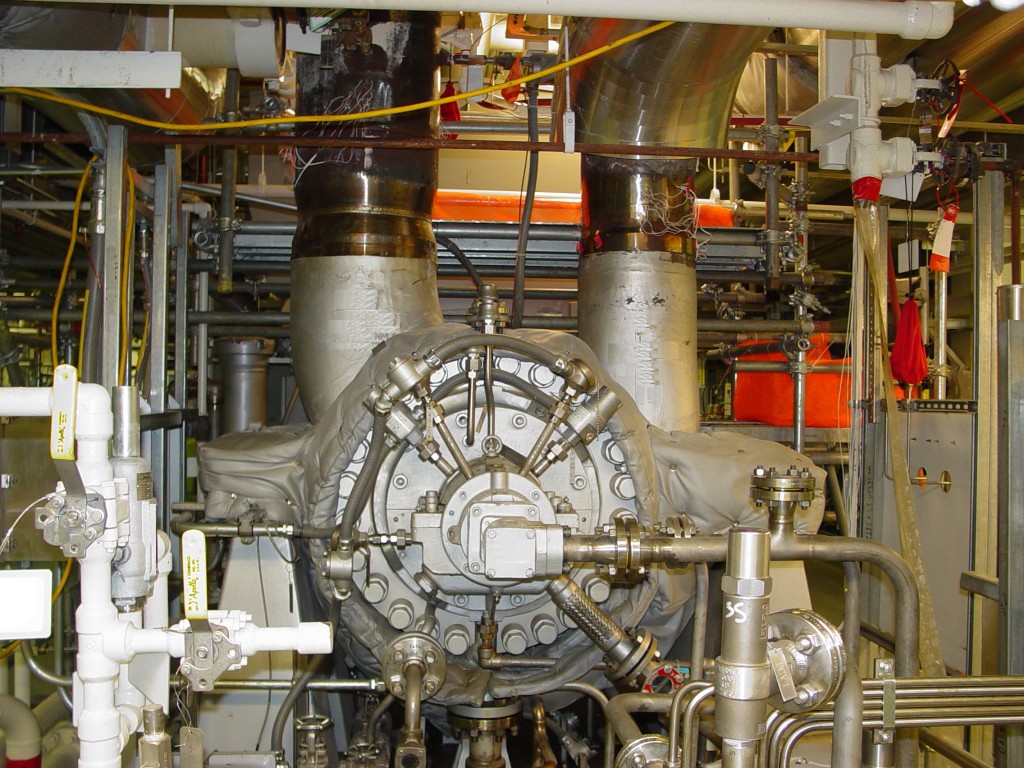
Figure 2. Example of oneODS animation developed based on measured test data (it is not an FEA model) showing the exaggerated but to scale motion of the pump system during operation.
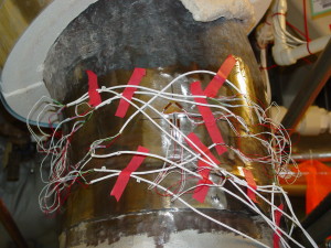 Figure 3. The use of strain gauges is very common when testing in a controlled environment. MSI uses strain gauges in the field to help measure: pipe strain, shaft torsional rotordynamics, and torque.
Findings & Root Cause
Key Observations:
- Excessive piping strain on suction and discharge nozzles caused high vibration (Figures 4 to 6).
- The pump casing acted as an anchor, transferring piping loads to the machine.
- Load-induced deflection pushed the south end of both pumps downward, changing pump-to-motor angular alignment.
- Phase angle changes at the DE of the Bravo Feed Water Pump indicated a rotor heavy spot shift.
Critical Note: No bearing damage or shaft overheating was observed, confirming mechanical integrity of the pump itself. The pump was the victim of pipe strain but it had not suffered significant damage.
Recommended Solution
MSI Engineering concluded:
- The Bravo Feed Water Pump could safely remain in service.
- During the next outage, correct the suction and discharge pipe loads based on further test data analysis.
- Realign pump and motor shafts after correcting piping loads.
This link goes to a good blog about how to avoid problems due to structural and acoustic pipe resonance.
This case history provides more information about correcting pipe stain problems.
Impact & Benefits
By pinpointing piping-induced strain as the root cause, the plant:
- Avoided an unnecessary shutdown, saving significant downtime and costs.
- Gained actionable recommendations to prevent future vibration issues.
- Demonstrated the value of advanced vibration testing and strain measurement in nuclear feed water pump maintenance.
- Laid a solid foundation for the follow-on problem correction effort.

Figure 4. Alpha Pump Discharge Pipe Bending and Torque loads.

Figure 5. Alpha Pump Discharge Pipe Axial Load

Figure 6. Top – Manufacturers will specify the maximum nozzle loads usually referencing a professional standard (in this case API 610 10th Edition). Bottom – Actual loads as measured by MSI. Rotating Machinery should never be used as a pipe anchor.
