Dynamic Mechanical Analysis: Mechanical Solutions, Inc. (MSI) performs pump casing structural analysis typically under contracts from rotating machinery manufacturers (pumps, compressors, fans, turbines, et al.). The starting point includes drawings or solid models, materials of construction information, operating conditions, and a discussion about any unusual concerns or issues. MSI uses Pro/Engineer or SolidWorks for solid modeling. Finite Element Analysis (FEA) codes used include ANSYS, NASTRAN, and Pro/Mechanica. Typically, ANSYS is used particularly if a non-linear analysis is required or if fluid-structural interaction (FSI) evaluations using unsteady (or transient) Computational Fluid Dynamics (CFD) code are needed.
An example of a pump casing analysis involved a horizontal pump in a critical slurry service. In this example, the analysis focused on evaluating the stress and deflection of a casing when operating under full pressure with various specified nozzle loads. The model included the suction/ discharge volutes, nuts and bolts, and back plate (Figure 1). To determine the structural integrity of the casing design under internal pressure and nozzle loads, a detailed finite element analysis was conducted with the model including the slurry pump casing, the respective hub disc cover (back plate), nuts and bolts, and suction/ discharge volute provided by the customer. The solid model assembly of all the parts was analyzed using ANSYS.

|

|
Figure 1. Plot of finite element mesh of the pump assembly. The mesh is composed of 1 million elements.
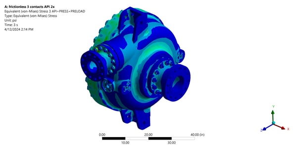
Nonlinear contact analyses were performed with the hub disc cover and the suction/ discharge scrolls bolted to the casing. The peak von-Mises stress of the assembly, and the peak stress locations, were determined and compared to stress criteria per ASME B&PV Code Section VIII, Division 2. Using stress linearization techniques across the pump casing at this peak stress location, the membrane and membrane-plus-bending stresses were below their respective allowable limits. The local peak stresses were determined to be acceptable. In this example, there were no significant oscillating loads present so a fatigue analysis was not performed. In other cases, MSI performs fatigue analysis, plotting the results on a Goodman diagram to evaluate life. In addition, the studs used on the back plate, suction scroll, and the discharge scroll were all determined to be sufficient relative to securing the parts subject to an internal operating pressure. Based on the analysis results, MSI recommended that the pump casing design was structurally adequate to meet the operating pressure condition combined, with the specified nozzle loads.
MSI was also called upon to perform a more detailed transient thermal analysis of an entire assembly to predict the start-up temperature distribution, casing/ shaft deformation, and fatigue life. Key deliverables included thermal gradient plots of the pump casing assembly for the optimized design, and the deformation at several specified temperature and operating pressure conditions. Fatigue evaluation involved applying fracture mechanics and Low Cycle Fatigue (LCF) analysis.
|
|
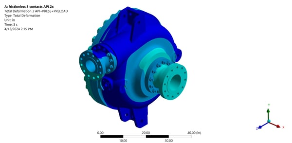
Figure 2. Left - von-Mises stresses (psi) of the pump assembly, with the specified pressure and nozzle loads applied, are compared to ASME Sect VIII, Div 2 operating limits. Right - Total deformation of the pump assembly under operating pressure and nozzle loads.
