A computer circuit board with a high clock speed processor chip was analyzed in an effort to establish the effectiveness of the cooling system. Processor chips can run too hot and their performance can deteriorate as a result. Different geometries for heat sinks and cooling fan locations can be analyzed in order to optimize chip cooling performance.
For this fluid—thermal Finite Element Analysis (FEA) case study, the particular design analyzed incorporated a high capacity cooling fan that draws air over an aluminum heat sink attached to the chip. The heat sink was a multi-tower design. The power of the processor chip could not be dissipated in the circuit board it was attached to, and all of it needed to be transferred efficiently to the air currents produced by the cooling fan.
 Particle flow streamlines for thermal—fluid FEA analysis of processor heat sink
The CFD capabilities of the ANSYS Multiphysics program were used to calculate simultaneously the fluid flow velocities throughout the computer case and the steady-state temperature distribution throughout the electronics. The fluid and non-fluid regions were solved together as a conjugate heat transfer problem. A finite element mesh was generated of the entire system, including a section of the motherboard, the processor chip, and the heat sink, as well as several of the attached electrical components and connectors. Each electrical component was assigned the appropriate thermal material properties, and the properties of dry air were assigned to the fluid. A heat source was distributed realistically within the processor chip, and a velocity was imposed on the fluid nodes at the location of the fan blades.
An on/off transient solution was then calculated, following which the flow and temperature results were animated. The analysis concluded that flow was indeed encouraged through the fins of the heat sink. The temperature distribution throughout the heat sink once it had reached steady-state is shown in the below animation. The optimized cooling system was found to be efficient enough to keep the hottest point in the processor chip below 136°F surface temperature, slightly below the 140°F desired.
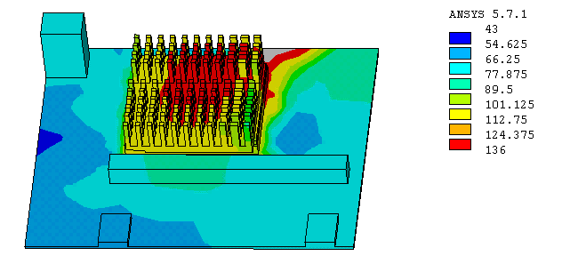 FEA animation of circuit board heat sink temperature distribution
If you would like an additional case study on circuit board structural analysis, please click here.
