MSI was contracted by a customer to investigate the source of high displacement vibration at the top of an absorber column (220 feet tall and 13 feet diameter) at low frequency and high displacement (6 inches displacement peak-peak). This high vibration caused the following issues:
- Efficiency reduction.
- Damage to internal components, such as downcomers, chimneys, and trays.
- Additional maintenance costs during every turnaround adding approximately 10 days of lost production.
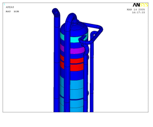
Figure 1. 3-D model of the 220 foot tall column, together with the main piping.
The purpose of the test and analysis was to determine the stresses at the nozzles and lower portion of the column. MSI’s plan was to determine excessive excitations, as well as to minimize the vibration by identifying and detuning any resonant natural frequencies.
The ODS (Operating Deflection Shape) and modal impact test were performed on the column in order to determine behavior of the unit at different frequencies. MSI performed a detailed finite element analysis (FEA) to determine the overall natural frequencies and mode shapes, by creating a 3-D model of the column, together with the main piping and foundation (Figure 1). The real world test data and analysis results were overlaid, and indicated a similar natural frequency about 0.78 to 0.81 Hz corresponding to the first bending mode (Figure 2).
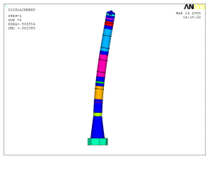
Figure 2. First bending mode of column 0.78 to 0.81 Hz in computer model. Test data was used to validate or anchor the model before potential solutions were modeled.
Trends in the process were reviewed versus column vibration trends. There was a close correlation between the level changes at the top tray of the column, and the vibration levels. Every time the level in this tray hit a range between 80-97% full, the vibration increased. Assuming a cylindrical storage vessel within the top take-off tray, the natural frequency of the internal waves, based on the main geometry, was predicted to be about 0.50 Hz, which was in the neighborhood of the 1st natural frequency of the column. The complete geometry of the top take-off section, including the gas pipes, downcomers, and the contribution of tangential motion of the solution coming from the top,resulted in the incoming flow having a swirl frequency which increased to 0.78 Hz when filled to the 80-97% range.
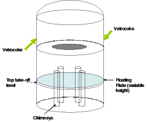
Figure 3. Floating plate "wave breaker".
Armed with this data, MSI then proposed the installation of a floating plate acting as a “wave breaker” at the top take-off tray section in order to detune the incoming wave’s swirling natural frequency from 0.78 Hz column swaying (Figure 3).
The cost of MSI’s troubleshooting and the repair was insignificant when compared to the production increase and reduction in maintenance costs.
