Mechanical Shock Analysis And Testing For Electronic Equipment
Electronic equipment installed on Navy ships must be ruggedized to withstand severe mechanical shocks and still continue to function. To ensure that this is the case, all such equipment must be shown to pass the requirements of Military Specification 901D. According to the specification, the severity of the mechanical shock exposure is dependent on the weight of the equipment, and other factors. One of three different tests applies: lightweight, medium weight and heavyweight. The lightweight and medium weight testing is performed with the equipment mounted on a test fixture and impacted by a swinging or dropping hammer. The heavyweight test is performed with the equipment mounted on a floating barge while underwater explosives are set off nearby, like this test for an aircraft carrier.
That Sounds Expensive – What About Modeling And Simulation?
Designing, prototyping, and testing ruggedized electronic equipment requires significant development time and expense, and failing the 901D testing is costly to the OEM. Modeling and simulation can reduce that cost- and schedule-risk by identifying structurally susceptible locations in the assembly and allowing them to be corrected before prototyping and testing. In certain limited cases, the U.S. Navy allows equipment to be qualified by analysis alone using the Dynamic Design Analysis Method (DDAM). This method is based on a shock response spectrum.
But Does DDAM Work? Show Me!
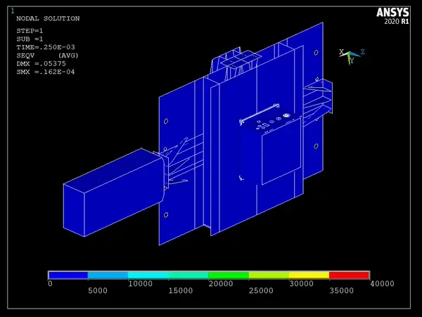
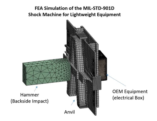
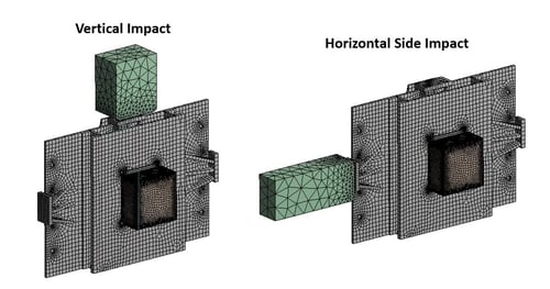
MSI has performed both time transient analysis and response spectrum analyses (DDAM) for OEMs of ruggedized equipment to simulate the lightweight shock test using Finite Element Analysis (FEA). One example case was an electrical enclosure with multiple internal circuit boards. Depicted in the figures are the FEA models of the lightweight test fixture with an OEM electrical box attached. The models are set up for the three orthogonal shock input directions, and include the hammer, anvil, and anvil spring supports. The transient response was calculated for each, and the stresses and deflections were monitored.
Locations of high stress were identified in various locations, including tall structural standoff posts that supported the internal elevated circuit board. This allowed designers to implement design modifications early on that greatly increased the likelihood of passing the shock testing.
DDAM analyses are fundamentally different in that they are performed in the frequency domain, and the participating natural modes in the response are combined together. In this case, the DDAM results were found to be similar to the transient simulations, in that stresses far exceeding yield were predicted in the specific locations high stress.
To learn more about MSI's advanced Finite Element Analysis capabilities, and how our modeling and simulation capabilities can help your product development efforts, click the link below.

