Avoiding Structural & Acoustic Pipe Resonance
By Bill Kelly
|
An example of a piping structural resonance at 358 Hz using MSI's VibVue® Motion Magnification solution |
MSI often troubleshoots issues of unacceptable pipe vibration and noise, like the piping structural resonance VibVue® video to the right at 358 Hz. It is a common and costly problem in new machinery installations, and resolving it after installation is not the best approach. Analysis can be cost-effectively performed in the design stage to significantly reduce risk, as long as it’s done to properly account for the physics of the fluid-structural interaction between the pipe and its contents.
Typical examples are when pipe structural bell (i.e. ovalizing) modes, or acoustic natural frequencies in discharge or suction piping, get excited by vane pass pulsations of a pump. If the run of pipe happens to be just the right length and diameter, a damaging structural or acoustic resonance can occur. Even worse would be if these two effects coincide at the same frequency.
"As modes become more complex, the manual analytical predictions become less accurate. A more rigorous approach is a fluid-structural coupled-field finite element analysis (FEA)." |
To accurately predict structural and acoustic modes, their interaction must be accounted for. Structural modes reduce in frequency due to increasing weight of the contained liquid. Acoustic modes reduce in frequency due to the increasing flexibility of piping. To correctly account for these effects, manual calculations can be performed. Equations exist for predicting the shift of acoustic frequencies based on internal fluid density, pipe diameter, and wall thickness. Also, mass effects on structural modes can be approximated by artificially increasing the density of the pipe. As modes become more complex, the manual analytical predictions become less accurate. A more rigorous approach is a fluid-structural coupled-field finite element analysis (FEA). The ANSYS workbench environment provides an interface for setting up and solving such a problem. The Modal Acoustics analysis system is invoked for predicting acoustic-structural natural frequencies, and the Harmonic Acoustics system allows for displacement, stress, and pressure amplitude predictions.
Structural Resonance Comparison
As an example, a straight run of 20 inch diameter pipe, 0.25 inch wall, 10 feet long, is analyzed between a pump and a reservoir. If the internal water is not accounted for, the first structural bell mode of the pipe is predicted by FEA at 116Hz. Using the Modal Acoustics solution, and accounting for the internal water reduced the predicted frequency to 66.2 Hz, a 42% reduction. The frequency of the second bell mode (three-lobed mode) also reduced by a similar amount. If these calculations were made by lumping the internal water mass into the pipe and performing a pure structural pipe analysis, the frequency predictions would be off by 6% for the first mode, and 10% for the second mode, which can spell trouble if the frequencies are near vane pass frequency.
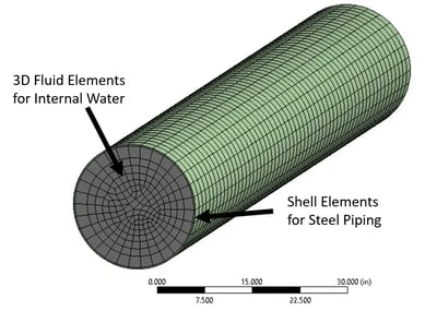
 Structural-Acoustic FEA model of steel piping filled with water
The above FEA deformation animation demonstrates the first structural bell mode of the pipe, with the left analysis not accounting for the internal water, and the right analysis accounting for it. Note the substantial shift in frequency from 116 Hz (without water) to 66 Hz (with water).
The above FEA deformation animation demonstrates the second structural bell mode of the pipe. Note the substantial shift in frequency from 205 Hz (without water) to 123 Hz (with water).
Acoustic Resonance Comparison
Continuing with this example, the pipe was assumed to be open at the reservoir end, and closed at the pump end. This open-closed boundary condition would yield 1/4 , 3/4 , 5/4 , … acoustic wavelengths. Manual calculations of the acoustic frequencies without accounting for pipe flexibility yielded 122 Hz and 365 Hz. The Modal Acoustics solution yielded frequencies approximately 25% lower than these as a result of the pipe flexibility. These shifts in acoustic frequencies correlated well with analytical predictions.
The second acoustic mode of the pipe at ¾ wavelength above shows a dramatic change in frequency from rigid pipe at 364 Hz to flexible pipe at 266 Hz
Why It Matters
More complex pipe networks, with bends and stiffening flanges would be even more accurately handled by this FEA technique rather than simplified manual calculations. With these types of models in hand during the design stage, what-if scenarios can be considered to ensure that these harmful structural and acoustic resonances are avoided prior to installation.
If you would like to learn more about the advantages of analyzing your system for potential natural frequency issues BEFORE installation, check out the case studies below. And if you would like MSI to help you solve your problem before it happens, Contact Us and we will be happy to help you.
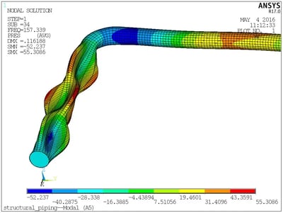
 Complex piping like this example ultimately means complex manual calculations, and is best handled with FEA as prescribed above


