Unique Pump Pipe Resonance Testing in a Nuclear Power Plant
Summary
What was the pump’s problem?
Bearings and seals were prematurely failing in a safety-related Decay Heat Removal (DHR) pump at a nuclear power plant. The pump was a single-stage, end-suction volute pump (Figure 1), and repeated failures raised concerns about equipment reliability and compliance with Nuclear Regulatory Commission (NRC) requirements.
What Were the Final Results?
- Permanent resolution of chronic pump failures
- 25× reduction in vibration amplitude at the vane pass frequency
- No Plant shutdown required
- No major piping modifications
- No system requalification required
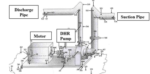
Figure 1. Decay Heat Removal (DHR)Removal Pump and Piping System Showing Locations Where Test Data Was Non-Intrusively Collected.
What Caused Excessive Vibration and chronic seal and bearing failures in the Decay Heat Removal Pump?
Initial Operating Deflection Shape (ODS) testing revealed that the pump casing was undergoing severe dynamic distortion. The dominant excitation frequency corresponded to the impeller vane pass frequency interacting with the volute tongue.
This excitation caused a vertical “bouncing” motion of the oversized discharge pipe, which dynamically loaded the pump discharge nozzle and distorted the pump casing—directly contributing to bearing and seal failures.
How Did ODS and Modal Testing Identify Pipe Resonance?
MSI also performed TAP™ Experimental Modal Analysis (EMA or Impact) testing on the pump and discharge piping while the pump was operating. The test identified a structural natural frequency dominated by vertical motion of the discharge pipe.
This natural frequency was nearly coincident with the first harmonic of the vane pass frequency and exhibited low damping pipe structural resonance condition.
Was the Pump or the Discharge Piping the Real Problem?
Plant engineers and NRC regulators needed confirmation that pipe resonance, not a pump design flaw, was the sole cause of the elevated vibration levels.
Direct measurement of pressure pulsation was problematic due to constraints:
• No pressure taps were available near the pump discharge
• Installing taps would violate safety-related piping
• Piping requalification could force a plant shutdown
At the same time, unresolved pump failures could also result in forced outage without quantitative proof of resolution.
How Did MSI Measure Pressure Pulsation Without Intrusive Pipe Taps?
MSI applied a non-intrusive vibration-based pressure pulsation measurement technique, previously used in nuclear, refinery, fan, and compressor systems.
The method involved mounting four very high frequency uniaxial accelerometers around the pipe circumference at 90-degree intervals. When placed away from flanges and supports, this configuration allowed MSI to:
• Separate radial pipe expansion caused by acoustic pressure pulsation
• From gross structural pipe vibration acting as rigid-body motion
Shell modes were ruled out due to their much higher frequency range (order of 1kHz).
How Was the Pipe Resonance and the Root Cause Verified Using FEA?
Pressure pulsation was non-intrusively measured one pipe diameter downstream of the pump discharge nozzle. MSI then calibrated a finite element analysis (FEA) model using the test data.
The FEA confirmed that the measured pulsation amplitude was sufficient to excite the discharge piping resonance at the vibration levels observed in the field—definitively identifying the true vibration source as the piping.
How Was Nuclear Pump Piping Resonance Eliminated Without Requalification?
MSI evaluated multiple mitigation strategies using the calibrated FEA model:
- Adding mass to the discharge pipe
- Installing piping dampers or shock absorbers
- Stiffening pipe supports
- Modifying pipe length
While effective, all options required full piping NRC requalification, which is costly and time-consuming in nuclear applications.
Instead, MSI designed a low-mass, tuned dynamic absorber (Figure 2):
- Thin-walled pipe “clamshell” surrounding the discharge pipe
- Adjustable vertical stiffness
- No penetration of the pressure boundary
FEA modeling and field testing confirmed the absorber quenched resonance at the vane pass frequency without requiring piping requalification or plant shutdown.

Figure 2. The non-intrusive adjustable tuned vibration absorber is conceptually shown above. Even with the use of FEA for the design it is recommended that the device also be easily adjustable while installed.
 Figure 3. The result was a 25x reduction in vibration amplitude without any major modification. Originally there was a single peak mode indicating failure-causing resonance. The vibration absorber creates the double-peak modes shown above. Fortunately the pump was driven at a constant speed.
FAQ
What caused the structural pipe resonance in this nuclear power pump system?
Pipe structural resonance occurred when pressure pulsation frequencies align with the structural natural frequency of the piping, resulting in excessive vibration. Information about both structural and acoustic piping natural frequencies and resonance is available in this blog.
How is pump vibration testing performed in nuclear power plants?
Techniques include Operating Deflection Shape (ODS) testing, modal impact testing, video vibration analysis, and non-intrusive pressure pulsation measurement.
Why are pressure taps avoided in safety-related nuclear piping?
Installing pressure taps can violate safety classifications and require costly requalification and regulatory approval.
Can pipe resonance be fixed without requalifying nuclear piping?
Yes. Tuned dynamic absorbers can mitigate resonance for constant speed machinery without modifying the pressure boundary, avoiding requalification.
What is TAP™ modal testing?
TAP™ is MSI’s proprietary Time-Averaged Pulse modal testing method that enables accurate modal analysis while equipment remains in operation.
