The Civil Engineers at a major Architect/Engineering firm used MSI’s experience and modern methodology to determine the effect of the suction and discharge piping on the structural natural frequencies of a dry-pit non-clog vertical pump which was due for replacement. Pump OEMs will understandably limit their own analysis efforts to the scope of their supply, and may not include piping effects and/or will assume the floor is infinitely stiff (it isn't). While leaving out system effects may be fine for a rotordynamics analysis, it makes a structural analysis misleading at best. The goal of a properly performed structural analysis is to ensure that the pump and associated components will not vibrate based on how the pump, motor, and associated system elements will be installed and behave in the system at various performance conditions.
In this case, by determining the effect of the suction/discharge on the natural frequencies of the currently installed pumps, the importance of including this piping in future finite element analysis (FEA) analysis predictions for the new pumps could be quantified. The Architect/Engineering firm could then be sure to state in their specification that the suction and discharge piping should be modeled explicitly in any future FEA calculations.
Based on MSI pump engineer’s FEA models of the full pump assembly, including the suction and discharge piping modeled out to the first rigid support, it was predicted that the added stiffness of the suction and discharge piping did not have a great influence on the 1st bending “global rocking” modes (up to 3.05%), however, the piping had a fairly significant influence on the 2nd bending “C-shaped” modes, up to 18.5%. For this reason, MSI engineers highly recommended that the Architect/Engineering firm include language in their specification that detailed models of the suction and discharge piping (up to the first rigid support) should be included in any structural natural frequency calculations of the future pump system.
The following table is a comparison of baseline modes and “disconnected suction/discharge piping” modes of a dry-pit non-clog vertical pump assembly in order to evaluate the effects of the suction and discharge piping.
| Dry-Pit Non-Clog Vertical Pump Structural Modes: Assessment of Suction/Discharge Piping Effects | |||||
| Pump Speed (RPM): 1070-1170 | |||||
| Description | Baseline FEA Predicted Natural Frequency | Natural Frequency without Stiffness Influence from Piping | Percent Influence of Piping | ||
| Hz | CPM | Hz | CPM | % | |
| 1st Bending "Global Rocking" Mode Perpendicular | 16.9 | 1,014 | 16.4 | 984 | -3.05 |
| 1st Bending "Global Rocking" Mode Parallel | 18.4 | 1,104 | 18.3 | 1,098 | -0.55 |
| 2nd Bending "C-Shaped" Mode Perpendicular | 29.4 | 1,764 | 24.8 | 1,488 | -18.5 |
| 2nd Bending "C-Shaped" Mode Parallel | 30.8 | 1,848 | 27.3 | 1,638 | -12.8 |
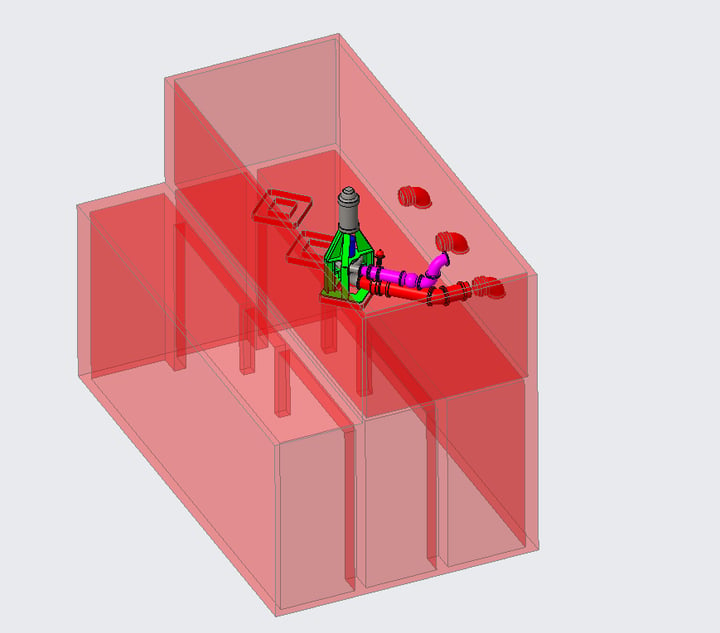
The following image is a Creo 4.0 solid model of the dry-pit non-clog vertical pump assembly used to match the structural natural frequencies measured by the MSI field testing team. It should be noted that to obtain a good match with the field measured structural natural frequencies, it was necessary to include the suction/discharge piping, modeled in 3D and fixed at the first rigid support.
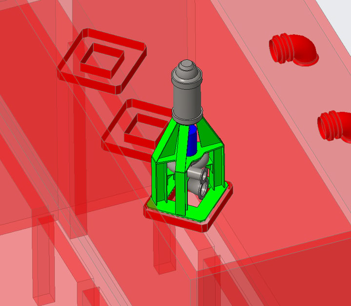
For comparison purposes, what follows is a Creo 4.0 solid model of the dry-pit non-clog vertical pump assembly used to assess the effects of the suction and discharge piping on the pump structural natural frequencies. It should be noted that the boundary conditions shown above are utilized only for comparison purposes. The correct configuration when performing a pump system structural natural frequency analysis is shown in the first image with a complete model of the surrounding system, including the suction and discharge piping.
Let's take a more detailed look at the 2nd Bending "C-Shaped" Mode, where the shift in natural frequency was significant. The following animation compares the 27 Hz forced response of the no piping model with the correctly modeled system, including suction and discharge piping.
2nd Bending "C-Shaped" Mode response at 27 Hz with no piping
Forced response at 27 Hz for model including piping showing minimal response
The following chart demonstrates the shift in the 2nd bending mode from 27 Hz to 31 Hz with a properly modeled system, including the piping.
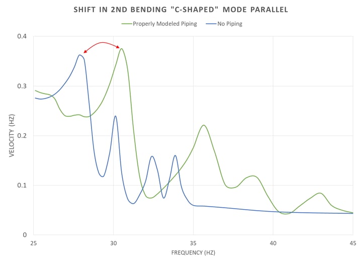
Finally, the properly modeled forced response at 30.8 Hz is shown, which was not evident using the no piping assumption.
2nd Bending "C-Shaped" Mode response at 31 Hz with piping included
Check out these related case studies to see how the foundation and water level affect your pre-installation analysis as well.
If you would like to discuss pre-installation design assessment analysis for pump or other rotating machinery project with an experienced MSI Engineer, Contact Us.
