Not an Off-the-Shelf Item
Many engineers view bearings as standard commodities with stock sizes readily available. Bearing catalogs often present life calculations and defined load ratings to predict a bearing’s performance. Though it would be convenient to offer standard sizes and prediction formulas, the design of foil bearings is more complex. Too many variables need to be factored into the foil bearing design to allow for stock selection.
System-Level Approach Required
Many factors need to be taken into account when designing a foil bearing for a new device. Because some of these factors are ingrained in the details of the machine’s layout and design, a “one size fits all” approach cannot be taken. That’s why we work with our customers to provide the bearing solution their system needs, based on our extensive experience developing many rotating machinery systems in general, and foil bearing in particular.
The bearings are an integral part of the machine system as a whole, and as such, a fully integrated design is necessary. Therefore, designing the bearings in parallel with the machine is the best way to achieve an integrated design. Including the bearings in the conceptual design phase will most effectively and efficiently yield an optimum design. That’s why we encourage our customers to get us involved at the earliest possible stage. Though retrofitting foil bearings in systems that were initially designed around other bearing systems is possible, often times there isn’t ample space available for the bearings, or other compromises need to be made to enable their use.
What You Need to Consider
The first thing an engineer needs to consider is whether foil bearings are appropriate for their application. Light to moderate loads (15 to 30 psi unit loading on the bearing), high speed (>10,000 rpm or >100 feet per second), and tolerance to low stiffness (deflections of 0.001-0.002 inch axially and radially) are general attributes essential for a well-designed foil bearing system.
In addition to these primary attributes, there are two fundamental areas that are critical to successfully designing a machine with foil bearings.
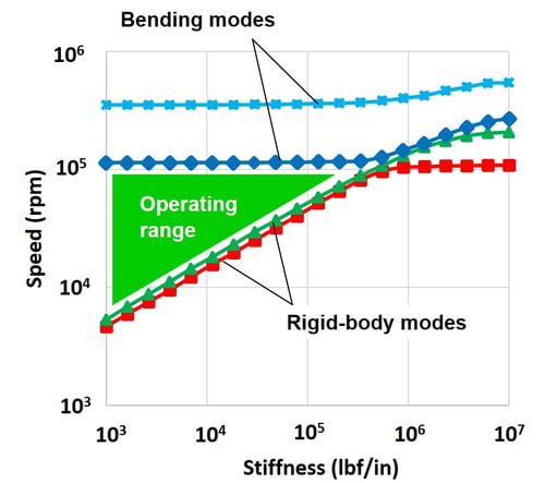
Rotordynamics – As with any rotating system, the dynamics of the rotor must be considered to guarantee stable operation with low vibration. Foil bearings are relatively soft compared to other bearings, and thus the rigid body modes tend to be low. Because of their low damping characteristics, the operating speed should have ample margin away from these modes, and in general should not cross the first bending mode. These criteria, when designed around appropriately, can define a fairly wide operating speed range.
The chart below shows a typical critical speed map of a foil bearing rotor system, with the acceptable operating zone identified.
Bearing Cooling – Even though gas foil bearings have relatively low frictional torque due to their non-contacting nature, it is not negligible and can often be surprisingly high. This is especially the case for large diameter bearings or machines running at very high speeds. Complete bearing systems (containing two journal bearings and a double-acting thrust bearing) can generate hundreds of watts of heat, and in some cases more than a kilowatt. Thrust bearings are usually the primary contributors due to their larger diameter.
If the amount of heat generation is low enough, the bearings can be passively cooled. This is achieved through convection to other surfaces, driven by the rotating components, and conduction to the outside surfaces, where it can be removed through natural or forced convection (e.g. a finned outer surface, with or without forced-air cooling, or a water jacket). Higher heat loads will often require active bearing cooling. This is achieved by allowing some of the process fluid (air, refrigerant, etc.) to flow through the system, allowing the heat to be carried away. The heated gas can then transfer its heat to other cooler components, or get expelled from the machine. In open air systems, the heated air can be vented to atmosphere, while in closed-loop systems, such as in refrigeration cycles, the gas is collected and passes through the system’s heat exchangers.
We Can Help
Developing an integrated design that factors in these areas will ensure a robust design. If you would like our help designing a bearing solution for you, just like we have for many others, don’t hesitate to get in touch. And we can help with the design of your entire rotating machine as well.