

A newly installed Air Cooled Condenser (ACC) fan guard or screen at an 1100 MW electric power generating station had a failure where plates (bat wings) connect the guard to the fan ring (shroud) structure(Figure 1). The failure occurred after approximately 80 hours of operation.
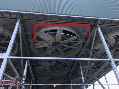
Figure 1. The 7 bladed fan was inoperable due to potential safety issues with the failed connection plates between the fan guard and the structure increased plates. The 40 foot diameter fan can be driven at two speeds via an induction motor and a gear reducer.
There were a total of 15 duplicate ACC fan cells but only one had failed. The failed fan could not be operated for safety reasons even for testing purposes. Based on experience, MSI suspected the failure was caused by a structural natural frequency that was resonant at the Blade Pass Frequency (BPF) or 7x rpm. There were expected small variations in natural frequency even though the fans themselves were duplicates so enough fans had to be tested to reasonably bracket the natural frequencies of interest on the failed fan based on testing the non-failed fans. Additionally, there was interest in determining how close the non-problems fans were to a resonant condition as the plant aged.
Vibration data were gathered on eight fans to help the troubleshooting process. Natural frequencies and their respective damping was approximated using FFTs. More detailed testing was performed on four fans as summarized below. Finite Element Analysis calibrated with the test data was used to design the most practical and effective solution.
The vibration tests performed by MSI included: Motion Magnified Video (MMV, VibVue®), impact modal “TAP™” testing, and Operating Deflection Shape (ODS) testing.
MSI’s VibVue® Motion Magnification Video (MMV) testing conducted on three cells indicated that the fan guard structure was swinging mostly in the perpendicular direction to the main I-beam along with the “waving” motion of the fan ring (shroud) every time a blade passed through. This is the typical aerodynamic pressure pulsation between the blade tip and the shroud at the Blade Pass Frequency (BPF), and usually, not a problem unless a structural component has a lightly damped natural frequency near BPF. See the magnified videos in Figures 2 and 3.
Figure 2. Magnified video of the problematic mode is shown. Note the fan guard structure motion relative to the main I-beams at Blade Pass Frequency (BPF) when the fan is operating at the higher of two speeds.
Figure 3. Zoomed view of the fan ring indicated waving motion every time the blade is passing through. MSI concluded via test and FEA that this mode was resonant in the fan cell with the failed guard connection. It is near resonance on several other fan cells.
Impact testing on one cell determined that the main lateral structural natural frequencies (in-line and perpendicular swing motion) were detected to have a less than 10% separation margin from BPF at the higher operational speed (see test data mode shape animations in Figure 4). Frequency Response Function (FRF) plots from the impact test were also analyzed carefully. This confirmed that the problem’s root cause was a structural resonance at BPF when the fan operated at the higher running speed.
Based on MSI’s experience, the minimum separation required is 10%, when it is measured in the field. FEA-based prediction requires at least a 15% separation margin to take into account FEA’s assumptions and uncertainties.
Figure 4. Animated impact test data confirms the video observation and provides data used to later calibrate the fan system “as built” FEA model. This animation shows an in-line (to the main support beams) mode that was on top of BPF. The perpendicular mode and the vertical trampoline mode were just above and below BPF, respectively.
ODS testing agreed with the video and impact test data indicating that the primary vibration of concern on all of the tested fans led to the guard connection failure. See Figures 5 and 6 for more details.
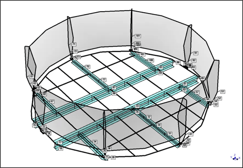
Figure 5. The labels indicate the 240 locations and directions where accelerometer data was collected for ODS testing. Data was collected on the support structure, fan guard, and shroud. One of the resultant animations is shown in Figure 6.
Figure 6. Animated ODS data confirms the video observation and provides data used to later calibrate the fan system “as built” FEA model. This animation shows the “orbiting” motion of the fan guard in the counter-clockwise direction with most of the motion perpendicular to the main I-Beams. This natural frequency is located at BPF and is suspected to be the primary resonance problem in the fan that suffered the failed fan guard support.
The next steps were to determine how to fix the vibration problem without resorting to trial-and-error problem-solving. The primary recommendation was adding stiffening to shift the offending natural frequency such that a margin of at least 15% from BPF is achieved.
Step 1 was to “calibrate” the FEA model based on the actual field vibration data (Figure 7). Step 2 was to iterate the FEA model with several detailed modifications so that a high-fidelity and practical fix (e.g., appropriate stiffening of the structure) could be specified and implemented (Figures 8 and 9).
MSI recommended the addition of bracing on each end of specific I-beams. Precise dimensions, material, and assembly information for the bracing were included in MSI’s final report. Figure 9 provides a depiction of the solution for the problematic fan cell guard.
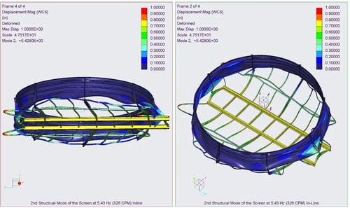
Figure 7. Step 1 - FEA model solution calibrated to match the test data (i.e., mimic the problem using FEA). This figure shows the mode at BPF that has in-line motion relative to the main I-Beam supports.
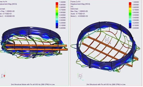
Figure 8. Step 2 – The final FEA model solution after several different stiffening approaches evaluated. This figure shows the same mode as shown in Figure 7 but it is now predicted to be 15% away from BPF. The vertical and perpendicular modes have separation margins of over 20%. Just as important the additional stiffening does not create another resonance issue at running speed or BPF for either fan rotational speed.
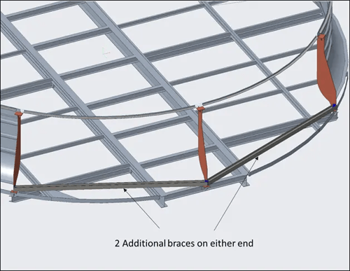
Figure 9. The recommended solution was to a) shift the offending natural frequency away from BPF without b) creating another resonance problem at either running speed and either BPF. MSI provided dimensional drawings and the other information needed so others could successfully implement the fix.
MSI also recommended that the fix be applied on several other fan cells where the measured separation margin indicated that a guard failure due to resonance would likely occur within the plant’s lifetime. Probably sooner rather than later based on the measured separation margin and damping data.

![]()
![]()
