

Vibration and Acoustic Risk With Evaluation (CWP): The Civil Engineers at a major Architect/Engineering firm used MSI’s experience and modern methodology to reduce the risk of future schedule- and budget-killing contractor change orders caused by vibration problems.
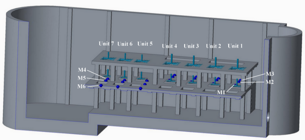
Figure 1. Pump Station Layout FEA Model
These vibration issues can and should be corrected by the 60% complete plant design phase, prior to installation. The customer (a major Midwest municipality) wanted to avoid repeating a previous negative experience. The pump station consisted of seven vertically mounted, constant speed sewage pumps with motors mounted on the floor above the pumps connected by vertical shafting.
MSI was tasked with providing a preliminary natural frequency analysis for the both the initial and future configurations to help ensure that the equipment operating frequencies would not excite the pump, motor, or support structure floor natural frequencies. Also, MSI performed a preliminary piping acoustic natural frequency analysis of the suction and discharge pipes to help ensure piping acoustic natural frequencies would not be excited by vane pass frequency during operation.
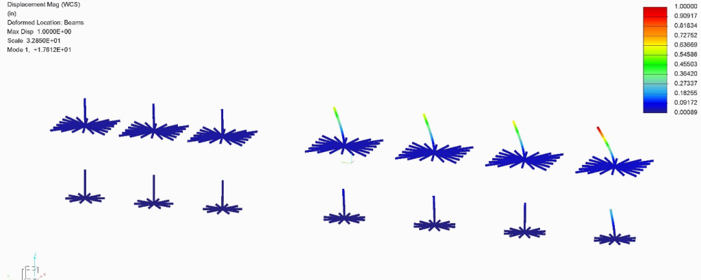
Figure 2. Finite Elements Analysis Beam Element First Natural Frequency Result
MSI developed an FEA model with beam models of the pumps and motors placed on the proposed foundation and MSI ran the analysis in both the initial and future pump and motor configurations with natural frequencies calculated up to 125% vane pass frequency. The analysis revealed potential for excitation of one motor in the initial configuration, and potential for excitation of another motor in the future configuration. Additionally, the 30% design phase foundation floors had the potential to be excited by running speed.
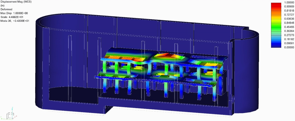
Figure 3. Motor/ Floor Structural Natural Frequency Mode Shape
The Engineer modified the design by adding additional columns and a honeycomb support structure below the slab. MSI’s new analysis indicated that floor-dominated modes were no longer in resonance. However, some pump and motor installed structural natural frequencies still had potential to be excited by running speed. MSI suggested adding an additional column and the Engineer agreed. The final FEA predicted that all motor and pump first mode natural frequencies were shifted to above 115% of running speed in both the initial and future configurations. Additionally MSI recommended advising the motor and pump manufacturers that a calculated minimum 3%‑7.5% reduction in equipment natural frequencies can be expected when mounting their equipment to the final foundation structure, as opposed to mounting to a rigid structure.
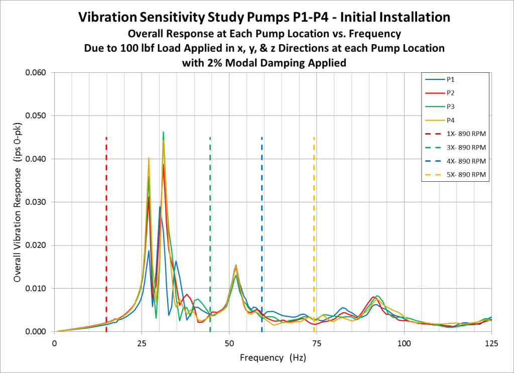
Figure 4. Vibration Sensitivity Study Plot

![]()
![]()