

A manufacturer of spinal implant systems had developed a new external-fixation clamping device to the stage that it was ready to undergo required compression-fatigue testing. Shortly before the testing commenced, the company requested that MSI predict through finite element analysis where the system initially would fail, and at what magnitudes of load. A successful evaluation called for test samples of the spinal implant to complete at least 5,000,000 fatigue load cycles without failure. The test standard required considerable amounts of time and expendable samples, both to establish the test’s parameters and to perform the subsequent fatigue evaluation. Accurately estimating the initial failure location and the cyclical failure loads would reduce the testing resources needed by the manufacturer substantially. The analysis also could provide insight into the complex interactions among the device’s structural components.
Nonlinear physical phenomena governed the operation of this device and greatly complicated its analysis. Friction and elastic deformation at the component interfaces held the system in position to transmit loads and limit overall movement. With increasing external loads, the potential for slippage between the parts escalated, as did the likelihood of plastic (permanent) part deformation. Slippage and plastic deformation would alter the load distribution throughout the structure, and plastic deformation would diminish the material’s fatigue resistance. These changes required the use of iterative nonlinear analysis techniques to evaluate the device realistically.
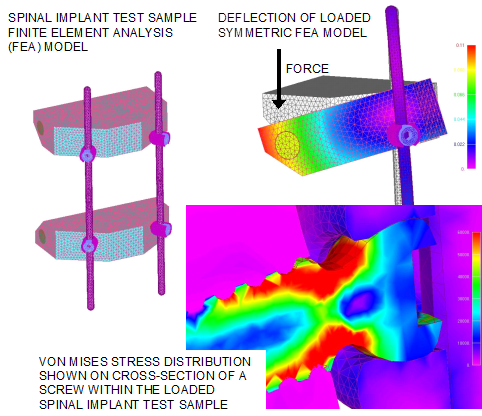
MSI simulated a typical test construct’s operation during a complete load cycle using finite element analysis (FEA). To replicate the external loads and constraints accurately, the detailed symmetric FEA model encompassed relevant portions of the test fixture along with the spinal implant test sample. An assembly preload effect was included to represent the internal clamping forces that held the implant system’s parts in position during the test. Contact elements that accounted for sliding friction were located at the component interfaces to reveal their interaction throughout the load cycle. Modeling the plasticity of the titanium alloy used to manufacture the components enhanced the nonlinear large-deflection solution’s accuracy.
MSI scrutinized the predicted maximum component stresses from the FEA results and identified where fatigue failure within the proprietary device was likely to initiate. By evaluating mean and alternating stresses with a modified Goodman diagram, MSI predicted analytical loads that would allow the implant to satisfy the fatigue test’s criterion, completing 5,000,000 load cycles without failure. MSI’s analysis also revealed otherwise difficult to observe details of the complex component interactions within the assembly. Fatigue testing performed by the manufacturer corroborated MSI’s analytical findings, and showed that both the initial fatigue failure location and the amount of load that would lead to failure were forecast accurately. The close agreement between the experimental and the analytical outcomes demonstrated that MSI’s finite element analysis expertise could be applied successfully as a tool to reduce mechanical testing costs, and to evaluate and refine spinal implant designs.

![]()
![]()